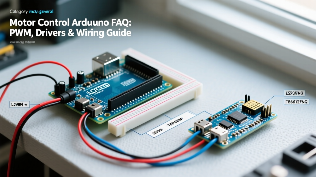

The Ultimate Quick Reference for Arduino Motor Control
Integrating motors into microcontroller projects is a rite of passage for every maker. However, moving from blinking LEDs to spinning DC gear motors or NEMA 17 steppers introduces complex electrical challenges: back-EMF spikes, voltage sags, and thermal throttling. In 2026, the maker market is flooded with advanced MOSFET-based drivers, yet many hobbyists still default to outdated BJT architectures that waste power as heat.
This FAQ and quick reference guide cuts through the noise, providing exact specifications, wiring topologies, and troubleshooting frameworks for motor control Arduino projects. Whether you are building a CNC plotter, an autonomous rover, or a robotic arm, this guide will help you select the right hardware and avoid catastrophic MCU resets.
Core Concepts: Why Microcontrollers Cannot Drive Motors Directly
A common beginner mistake is attempting to power a small DC motor directly from an Arduino Uno's digital I/O pins. The ATmega328P microcontroller has strict current limitations:
- Per-Pin Limit: 20mA recommended, 40mA absolute maximum.
- Total VCC/GND Limit: 200mA absolute maximum across all pins combined.
Even a micro coreless motor can draw 500mA on startup (stall current). Exceeding the GPIO limits will instantly fry the microcontroller's internal silicon traces. Furthermore, motors are inductive loads. When you cut power to an inductor, the collapsing magnetic field generates a massive reverse voltage spike (Back-EMF) that can easily exceed 50V, destroying sensitive logic circuits. You must always use a motor driver to isolate the low-voltage logic from the high-current inductive load.
Motor Driver Quick Comparison Matrix (2026 Edition)
Selecting the right driver depends on your motor's voltage, stall current, and efficiency requirements. Below is a comparison of the most common modules available to makers today.
| Driver IC / Module | Architecture | Operating Voltage | Continuous Current | Voltage Drop | Avg. Price (2026) |
|---|---|---|---|---|---|
| L298N | BJT Darlington | 5V - 35V | 2.0A per channel | ~2.0V - 3.0V | $4.00 - $6.00 |
| TB6612FNG | MOSFET | 2.5V - 13.5V (VM) | 1.2A per channel | ~0.5V | $5.00 - $8.00 |
| DRV8871 | MOSFET | 6.5V - 45V | 3.6A | Low (Rds-on) | $4.50 - $7.00 |
| BTS7960 | High-Power Half-Bridge | 5.5V - 27V | 27A (43A peak) | Extremely Low | $12.00 - $18.00 |
Pro-Tip: Avoid the L298N for battery-powered robots. Its BJT architecture drops up to 3V as heat, meaning a 6V motor will only receive 3V, drastically reducing torque and battery life. Upgrade to the TB6612FNG or DRV8871 for MOSFET-based efficiency.
Frequently Asked Questions (FAQ)
1. How do I control DC motor speed using PWM?
Pulse Width Modulation (PWM) simulates an analog voltage by rapidly switching the digital pin HIGH and LOW. On an Arduino Uno, the analogWrite(pin, value) function accepts a value from 0 (0% duty cycle / stopped) to 255 (100% duty cycle / full speed).
However, the default PWM frequency on most Uno pins (Timer0 and Timer2) is approximately 490Hz. When applied to a motor, this low frequency can cause the motor coils to vibrate audibly, resulting in an annoying high-pitched whine. To fix this, you can reconfigure the ATmega328P hardware timers to output an ultrasonic frequency (e.g., 20kHz or higher). According to the official Arduino analogWrite reference, pins 5 and 6 operate at 980Hz by default, but manipulating the TCCR0B or TCCR1B registers allows you to push the frequency well beyond human hearing, eliminating acoustic noise and improving low-speed torque.
2. Why does my Arduino keep resetting when the motor starts?
This is the most common failure mode in motor control Arduino projects. It is almost always caused by one of three issues:
- Voltage Sag (Brownout): Motors draw massive inrush current when starting. If the motor and Arduino share the same 5V voltage regulator or USB power bank, the voltage will temporarily dip below the ATmega328P's brownout detection threshold (usually 2.7V or 4.3V), triggering a hardware reset.
- Missing Flyback Diodes: Inductive kickback from the motor is feeding back into the logic rail. While most modern driver boards include onboard Schottky diodes, cheap clones sometimes omit them. Always verify their presence or add external 1N5819 diodes across the motor terminals.
- Ground Loops: High-current return paths from the motor are passing through the Arduino's delicate logic ground trace. Solution: Use a "Star Ground" topology. Connect the motor power supply ground, the driver board ground, and the Arduino ground at a single, dedicated physical point (like a terminal block), ensuring high currents never flow through the microcontroller's PCB traces.
3. How do I wire and tune a NEMA 17 Stepper Motor?
For steppers, H-bridges are replaced by dedicated chopper drivers like the A4988 or DRV8825. These drivers use a step/direction interface rather than raw PWM.
Wiring Quick Reference:
- STEP Pin: Connect to any Arduino digital pin. Each HIGH pulse moves the motor one microstep.
- DIR Pin: Connect to any digital pin. HIGH = Clockwise, LOW = Counter-Clockwise.
- MS1, MS2, MS3: Tie to GND for full steps, or configure for 1/8 or 1/16 microstepping to reduce resonance.
The Vref Tuning Formula (Critical for preventing melted coils):
You must set the current limit potentiometer on the driver before running the motor. Using a multimeter, measure the voltage between the GND pin and the Vref test point. The formula for the standard Pololu A4988 carrier is:
Vref = Current Limit / (8 × Rcs)
If your NEMA 17 is rated for 1.0A and the sense resistor (Rcs) on your board is 0.05Ω:
Vref = 1.0 / (8 × 0.05) = 0.4V.
Turn the tiny brass potentiometer until your multimeter reads 0.4V. Setting this too high will overheat the motor and the driver IC; setting it too low will result in missed steps and stuttering.
Troubleshooting Edge Cases & Failure Modes
When your circuit is wired correctly but the motor behaves erratically, check these advanced edge cases:
- Motor whines but won't spin at low PWM values: DC motors have a minimum "start voltage" required to overcome static friction and cogging torque. A PWM value of 50 (out of 255) might not provide enough average voltage. Implement a "kickstart" routine in your code: send a PWM value of 255 for 50 milliseconds to break static friction, then immediately drop to your desired low PWM value.
- L298N gets too hot to touch: This is normal for BJT drivers handling over 1A. The silicon junction is dissipating watts of heat. You must attach a passive aluminum heatsink or an active 5V fan. If thermal shutdown occurs, the internal protection circuitry will temporarily disable the H-bridge until it cools.
- Stepper motor vibrates violently at specific speeds: This is mid-band resonance, a known physical limitation of 2-phase bipolar steppers. To bypass this, enable 1/16 microstepping on your driver, add a mechanical damper to the motor shaft, or use acceleration ramps (via the
AccelStepperlibrary) to quickly sweep through the resonant RPM range.
Power Supply Sizing for Maker Projects
Never undersize your power supply. To calculate the required amperage for a multi-motor robotics chassis, use this framework:
Total Current = (Motor 1 Stall Current + Motor 2 Stall Current) × 0.75 + MCU Overhead (0.5A)
For a typical 2WD rover using 6V TT gear motors (stall current ~800mA each) controlled by a TB6612FNG and an Arduino Nano:
Total = (0.8A + 0.8A) × 0.75 + 0.5A = 1.7A minimum.
Always select a battery pack or BEC (Battery Eliminator Circuit) rated for at least 20% above your calculated maximum to prevent voltage sag during aggressive maneuvers. LiPo batteries (2S or 3S) paired with a high-efficiency buck converter remain the gold standard for high-current mobile robotics in 2026.
Further Reading and Authoritative Sources
To deepen your understanding of inductive loads and H-bridge topologies, consult the following engineering resources:
- Texas Instruments Motor Driver Overview - Excellent whitepapers on MOSFET vs. BJT thermal management and gate drive requirements.
- SparkFun TB6612FNG Hookup Guide - Detailed schematics and logic tables for modern MOSFET-based dual H-bridges.
By respecting the physics of inductive loads and selecting the appropriate driver architecture, you can transform your Arduino from a simple logic controller into a robust, industrial-grade motion control system.