
Beyond the Breadboard: Why Basic Potentiometer Circuits Fail in Production
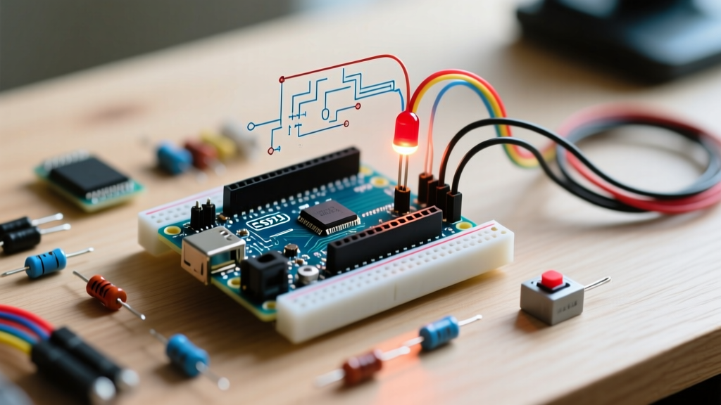
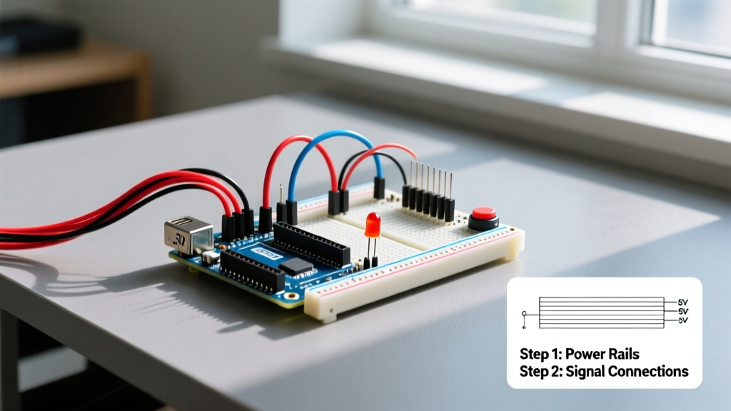
If you have ever followed a beginner tutorial for potentiometer control LED Arduino setups, you are likely familiar with the classic recipe: an Arduino Uno R3, a generic 10k carbon-track potentiometer, and a standard 5mm LED. The code relies on a simple analogRead() mapped to an 8-bit analogWrite() PWM output. While this works perfectly for a weekend prototype, migrating this exact circuit into a commercial product, an interactive art installation, or a high-end lighting rig will quickly expose severe hardware and software bottlenecks.
Carbon track potentiometers suffer from wiper noise, mechanical dead zones, and limited rotational lifespans. Furthermore, the ATmega328P microcontroller is limited to 10-bit ADC resolution and 8-bit PWM output. At low LED brightness levels (below 15% duty cycle), 8-bit PWM causes visible 'stepping' or flickering rather than a smooth fade. This migration guide details exactly how to upgrade your legacy potentiometer and MCU setup to a modern, high-resolution, and noise-immune architecture using 2026 best practices.
Phase 1: Hardware Migration Paths
The physical user interface is the most common point of failure in analog input circuits. Upgrading the potentiometer itself yields the highest immediate return on investment for signal integrity.
| Component Type | Specific Model (2026) | Approx. Cost | Resolution / Track | Lifespan | Best Application |
|---|---|---|---|---|---|
| Carbon Track (Legacy) | Alpha RD901F-40-15K-B10K | $0.85 | Analog (Noisy) | 15,000 cycles | Prototyping / Toys |
| Precision Wirewound | Bourns 3590S-1-103L | $14.50 | 10-Turn Analog | 25,000,000 cycles | Studio Audio / Lighting |
| Conductive Plastic | Bourns 3540HS-1-103A | $22.00 | Single-Turn Analog | 50,000,000 cycles | Industrial HMI Panels |
| Digital Potentiometer | Microchip MCP4151-103E/P | $1.95 | 257-step SPI | Infinite (Solid State) | Automated Calibration |
Deep Dive: The Bourns 3590S Precision Upgrade
For high-end lighting control where users expect buttery-smooth dimming, the Bourns 3590S series is the industry standard. Unlike single-turn carbon pots that map 300 degrees of rotation to a 0-5V sweep, the 3590S is a 10-turn wirewound precision potentiometer. This mechanical gearing effectively multiplies the physical resolution by a factor of ten, allowing users to make micro-adjustments to LED brightness that would be physically impossible on a standard Alpha pot. While the $14.50 unit cost is high for consumer goods, it is mandatory for professional stage lighting DMX-to-analog converters.
Expert Insight: When migrating to wirewound pots like the Bourns 3590S, be aware that the wiper moving across the wire windings creates quantized 'steps' in resistance. While vastly superior to carbon noise, this can still introduce micro-jitter in high-gain ADC circuits. Always pair precision analog pots with software-level filtering.
Phase 2: Microcontroller Migration for High-Res PWM
The legacy Arduino Uno R3 (ATmega328P) limits your LED control to 256 discrete brightness steps. Human vision perceives light logarithmically, meaning the jump from PWM value 1 to 2 is jarringly bright. To achieve true 1% dimming without flicker, you must migrate to a microcontroller capable of at least 12-bit PWM (4096 steps).
Migrating to the Arduino Nano ESP32
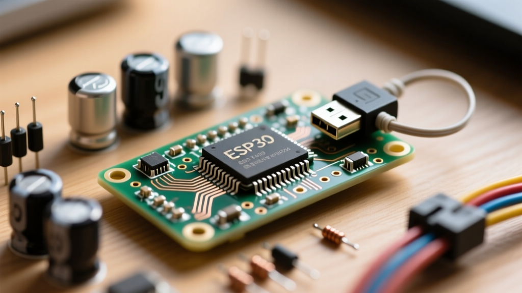
In 2026, the Arduino Nano ESP32 (priced around $21.00) is the premier drop-in upgrade for legacy Uno projects. It features a 12-bit SAR ADC (0-4095) and the Espressif LED Control (LEDC) peripheral, which supports up to 16-bit PWM resolution. By migrating to the Nano ESP32, you can map a 12-bit ADC read directly to a 12-bit PWM write, completely bypassing the destructive map(val, 0, 1023, 0, 255) compression that ruins low-end dimming.
Phase 3: Software Migration and the EMA Filter
Upgrading the hardware is only half the battle. High-resolution ADCs (12-bit and above) are incredibly sensitive to electromagnetic interference (EMI) and power supply ripple. A raw analogRead() on an ESP32 will often fluctuate by ±15 LSBs (Least Significant Bits) even when the potentiometer is completely stationary. If you map this directly to your LED PWM, the LED will visibly 'breathe' or flicker at rest.
Implementing the Exponential Moving Average (EMA)
Instead of using a simple rolling average (which requires storing arrays of past values and consumes precious SRAM), professional firmware uses an Exponential Moving Average (EMA) filter. The EMA applies a weighting factor (alpha) to the newest reading while retaining the historical inertia of previous readings.
// Modern ESP32 Core v3.x LEDC and EMA Implementation
const int potPin = A0;
const int ledPin = 9;
const float alpha = 0.15; // Lower = smoother but more latency

float filteredValue = 0.0;

void setup() {
  Serial.begin(115200);
  analogReadResolution(12); // Upgrade ADC to 12-bit (0-4095)

  // Configure LEDC: Pin 9, 5000 Hz frequency, 12-bit resolution
  ledcAttach(ledPin, 5000, 12);

  // Initialize filter with first raw reading
  filteredValue = analogRead(potPin);
}

void loop() {
  int rawValue = analogRead(potPin);

  // EMA Filter Math
  filteredValue = (alpha * rawValue) + ((1.0 - alpha) * filteredValue);

  // Direct 12-bit to 12-bit mapping (No data loss!)
  uint16_t pwmOutput = (uint16_t)filteredValue;

  ledcWrite(ledPin, pwmOutput);

  // Optional: Non-blocking serial telemetry for debugging
  static unsigned long lastPrint = 0;
  if (millis() - lastPrint > 250) {
    Serial.printf("Raw: %d | Filtered: %.1f | PWM: %d\n", rawValue, filteredValue, pwmOutput);
    lastPrint = millis();
  }
}
By utilizing the Espressif LEDC API via the modern ledcAttach() function introduced in ESP32 Arduino Core v3.x, we eliminate the deprecated channel-binding boilerplate and achieve hardware-level 12-bit dimming.
Real-World Failure Modes and Edge Cases
Even with precision hardware and filtered code, migrated circuits often fail in the field due to overlooked electrical edge cases. Address these during your PCB layout or wiring phase:
- VREF Instability: If you power your potentiometer from the MCU's 5V USB rail, any USB voltage drop (e.g., from a long cable or a hub) will shift the ADC reference voltage, causing the LED brightness to drift. Fix: Power the potentiometer from the MCU's dedicated 3.3V LDO output and use that same 3.3V line as the ADC VREF.
- Ground Loop Hum: If the LED driver shares a ground return path with the potentiometer, the high-current PWM switching of the LED will inject noise into the analog ground plane. Fix: Use a star-ground topology where the analog ground (potentiometer) and power ground (LED driver) meet at a single physical point on the PCB.
- Wiper Lift-Off: In high-vibration environments (e.g., automotive or stage rigging), the mechanical wiper of a physical potentiometer can momentarily lose contact with the track, causing the ADC input to float to an undefined state and the LED to flash at 100% brightness. Fix: Place a 100nF ceramic capacitor directly between the ADC wiper pin and GND to hold the voltage steady during micro-second lift-offs, or migrate entirely to solid-state Hall-effect rotary encoders.
Summary of the Migration ROI
Migrating from a basic potentiometer control LED Arduino tutorial setup to a production-grade architecture requires shifting from 8-bit to 12-bit domains, swapping carbon tracks for wirewound or conductive plastic elements, and implementing DSP-style EMA filtering. While the BOM cost increases from roughly $4.00 to $25.00 per unit, the elimination of flicker, mechanical wear, and ADC jitter transforms a hobbyist toy into a professional-grade lighting controller.