
Why Migrate from a Basic Force Resistor Arduino Circuit?
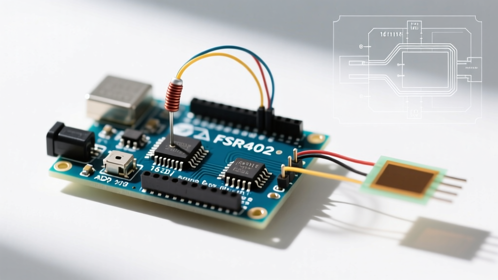
When makers first build a force resistor Arduino project—whether it is a MIDI drum pad, a robotic gripper pressure sensor, or a DIY smart scale—they almost universally start with the Interlink FSR402. It is inexpensive, widely available, and requires only a single pull-down resistor to interface with an Arduino Uno's analog pins. However, as projects move from the prototyping bench to real-world deployment in 2026, the limitations of this basic setup become glaringly obvious.
The standard voltage divider circuit paired with the ATmega328P’s 10-bit analog-to-digital converter (ADC) yields poor resolution at the extremes of the sensor's range, severe non-linearity, and susceptibility to electromagnetic interference (EMI). If your project suffers from signal drift, hysteresis, or an inability to detect micro-changes in pressure, it is time for a hardware and firmware migration.
Expert Insight: The most common mistake in force-sensing projects is treating a Force Sensitive Resistor (FSR) as a linear voltage source. An FSR is a variable resistor whose conductance (1/R), not its resistance, scales linearly with applied force. Upgrading your circuit and math model is mandatory for precision.
The Baseline: Understanding FSR402 Limitations
The Interlink 402 operates on a simple principle: as force increases, the conductive polymer particles compress, lowering the resistance from >1MΩ (unloaded) down to roughly 250Ω (at 10kg of force). When wired in a voltage divider with a 10kΩ pull-down resistor, the output voltage follows an exponential curve. The Arduino's 10-bit ADC maps the 0-5V range to 1024 steps (approx. 4.88mV per step). Because the voltage curve flattens out at higher forces, the last 50% of the sensor's physical capacity might only occupy 50 ADC steps, rendering high-force precision impossible.
2026 Sensor Migration Matrix
Before rewriting your firmware, you must decide whether to upgrade the analog front-end (AFE) of your existing FSR, or migrate to an entirely new sensor topology. The table below outlines the most common migration paths for force-sensing projects.
| Migration Path | Sensor / Hardware | Interface & Resolution | Linearity & Hysteresis | Est. Cost (2026) |
|---|---|---|---|---|
| Baseline | Interlink FSR402 + 10kΩ Resistor | 10-bit ADC (ATmega328P) | Poor (Exponential curve, high hysteresis) | $9.00 |
| AFE Upgrade | FSR402 + ADS1115 Breakout | 16-bit I2C ADC (860 SPS) | Moderate (Better resolution, same curve) | $14.00 |
| Sensor Upgrade | Tekscan FlexiForce A502 | Inverting Op-Amp Circuit | High (Tight hysteresis, linear voltage) | $28.00 |
| Full Migration | TAL220 Thin-Film Load Cell + HX711 | 24-bit Dedicated ADC | Excellent (True linear weight/force) | $18.00 |
Hardware Upgrade 1: Improving the Analog Front End (AFE)
If your mechanical design is already locked in and you must stick with the physical FSR402, your first migration step is abandoning the Arduino's internal ADC. The internal ADC has a high impedance mismatch and significant noise floor. By migrating to an external 16-bit ADC like the ADS1115, you increase your resolution from 1,024 steps to 65,536 steps.
Wiring the ADS1115 for FSR Interfacing
According to Adafruit's ADS1115 ADC Guide, the breakout board communicates via I2C and features an internal Programmable Gain Amplifier (PGA). This is critical for FSRs because the voltage swing at high pressures is very small.
- VDD to Arduino 5V (or 3.3V for ESP32/SAMD boards)
- GND to Arduino GND
- SCL / SDA to dedicated I2C pins (A5/A4 on Uno, GPIO 22/21 on ESP32)
- A0 to the FSR voltage divider midpoint
Configuration Tip: Set the ADS1115 gain to GAIN_TWO (±2.048V range). This effectively gives you 15-bit resolution within the specific voltage window where your FSR operates under load, resolving micro-changes in pressure that the standard Arduino analog pin would completely ignore.
Hardware Upgrade 2: Sensor Migration Paths
If your application requires medical-grade repeatability, industrial weighing, or robotic feedback where hysteresis is unacceptable, you must migrate away from conductive polymer FSRs entirely.
Path A: Migrating to Tekscan FlexiForce A502
The FlexiForce A502 is a piezoresistive sensor that looks like an FSR but behaves entirely differently. Unlike the FSR402, which is used in a voltage divider, the FlexiForce acts as a variable resistor in an inverting operational amplifier circuit. As detailed in SparkFun's FSR Hookup Guide and Tekscan's integration manuals, applying force to a FlexiForce decreases its resistance, which in turn linearly increases the output voltage of the op-amp. This yields a near-perfect linear response from 0 to 110 lbs, eliminating the need for complex logarithmic mapping in your Arduino sketch.
Path B: Transitioning to Thin-Film Load Cells (TAL220)
For projects like smart beds, heavy-duty scales, or structural stress testing, the ultimate migration is to a thin-film load cell like the TAL220 paired with an HX711 24-bit ADC. The TAL220 utilizes a Wheatstone bridge configuration. When force is applied, the micro-strain gauges deform, creating a millivolt-level differential signal. The HX711 amplifies and digitizes this signal. While the TAL220 lacks the ultra-thin profile of an FSR, it offers zero creep, temperature compensation, and true linear force measurement up to 50kg.
Firmware Migration: Rewriting the Arduino Sketch
Migrating your hardware requires a fundamental rewrite of your Arduino firmware. You can no longer rely on a simple analogRead() and a basic map() function.
Step 1: Implementing Conductance Math for FSRs
If you upgraded to the ADS1115 but kept the FSR402, you must convert the raw ADC voltage into resistance, and then into conductance. Force is proportional to conductance (G = 1/R).
- Read the 16-bit ADC value.
- Convert the ADC value to Voltage.
- Calculate the FSR resistance using the voltage divider formula:
R_fsr = (V_in * R_pull / V_out) - R_pull. - Calculate Conductance:
G = 1000000 / R_fsr(in micro-mhos). - Map the Conductance linearly to Force using a two-point calibration.
Step 2: Digital Filtering and Tare Routines
High-resolution ADCs will pick up 50Hz/60Hz mains hum and thermal noise. Implement a rolling average or a Kalman filter in your sketch. Furthermore, FSRs and load cells suffer from creep—the phenomenon where the sensor's resistance slowly drifts downward under a constant static load. Your firmware must include a 'tare' routine that samples the sensor at startup (or via a physical pushbutton) and subtracts the baseline offset from all subsequent readings.
Real-World Troubleshooting & Edge Cases
During migration, engineers frequently encounter specific failure modes. Here is how to resolve them:
- Ghosting in Matrix Arrays: If you are migrating a grid of force resistors (e.g., a pressure mapping mat) using multiplexers like the CD74HC4067, you will experience 'ghosting' where pressing one node registers force on adjacent nodes. Solution: You must add a Schottky diode (e.g., BAT54) in series with every single FSR in the matrix to block reverse current paths.
- Op-Amp Saturation: When migrating to the FlexiForce A502 inverting op-amp circuit, using a standard LM358 op-amp on a 5V rail will cause the output to saturate at ~3.5V, clipping your high-force data. Solution: Migrate to a rail-to-rail op-amp like the MCP6001 or power the LM358 with a 9V rail while using a voltage divider to step the output down to the Arduino's 3.3V/5V logic level.
- I2C Bus Lockups: When using the ADS1115 or HX711 in electrically noisy environments (like near stepper motors), the I2C bus can lock up. Solution: Add 4.7kΩ pull-up resistors to the SDA and SCL lines, and use twisted-pair shielded cable for the sensor leads.
Summary Checklist for Your Upgrade
Migrating a force-based project from a hobbyist prototype to a reliable 2026-standard device requires addressing both the physical sensor and the analog read chain. Evaluate your required precision: if you need repeatable, linear force data under $30, migrate to a TAL220 load cell. If you must maintain the ultra-thin form factor of an FSR, upgrade your AFE with a 16-bit ADS1115 and rewrite your firmware to calculate conductance rather than raw voltage. For deeper integration schematics and bridge amplifier designs, refer to the Texas Instruments INA125P datasheet, which remains the gold standard for conditioning thin-film strain gauges in microcontroller applications.