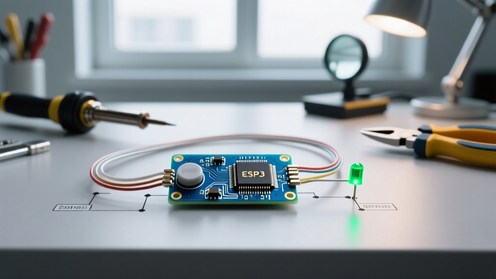

Beyond the Breadboard: The 2026 Migration Standard
Every embedded systems engineer and hobbyist begins their journey with the classic Arduino button and LED tutorial. Wiring a tactile switch to a digital input pin and toggling an output LED is the 'Hello World' of hardware. However, as projects evolve from weekend prototypes to robust, production-ready IoT devices in 2026, the traditional 5V polling method on an original Uno becomes a severe bottleneck. Blocking code, mechanical switch bounce, and 5V logic incompatibility with modern 3.3V sensors demand a strategic migration.
This guide provides a comprehensive upgrade path. We will migrate your foundational Arduino button and LED setup from basic polling on a legacy AVR board to a modern, interrupt-driven architecture using the ESP32-S3, incorporating hardware debouncing and professional PCB layout techniques.
Why Migrate from the Classic Setup?
The standard beginner approach relies on a while(1) loop continuously polling a GPIO pin using digitalRead(). While functional for a single LED, this architecture fails in complex systems for three primary reasons:
- CPU Blocking: Polling consumes 100% of the microcontroller's attention. If your main loop includes Wi-Fi stack management, sensor fusion, or display rendering, a 50ms button press might be missed entirely.
- Mechanical Bounce: Standard 6x6mm tactile switches exhibit contact bounce lasting 1ms to 5ms. Without proper handling, a single press registers as a dozen rapid triggers, destroying state-machine logic.
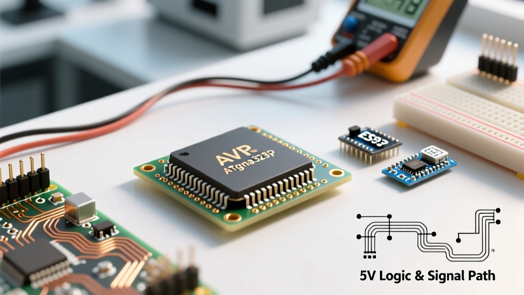
- Voltage Domain Clashes: The legacy 5V logic of the ATmega328P requires level-shifting when interfacing with modern 3.3V peripherals (like the BME280 or modern LiPo fuel gauges), adding BOM cost and board complexity.
Hardware Migration Matrix: Uno R4 vs. ESP32-S3
When upgrading your Arduino button and LED project, selecting the right target MCU is critical. Below is a comparison of migrating to the newer Arduino Uno R4 Minima versus the industry-standard ESP32-S3.
| Specification | Arduino Uno R4 Minima | ESP32-S3-DevKitC-1 | Migration Verdict |
|---|---|---|---|
| Core Architecture | Renesas RA4M1 (Cortex-M4) | Xtensa LX7 (Dual-Core) | ESP32-S3 wins for parallel RTOS tasks. |
| Logic Level | 5V | 3.3V | ESP32-S3 natively matches modern sensors. |
| Approx. Price (2026) | $27.50 | $8.50 - $11.00 | ESP32-S3 offers vastly superior cost-to-performance. |
| Internal Pull-Up | ~20kΩ - 50kΩ | ~45kΩ | Both require external 10kΩ for noisy environments. |
| Interrupt Pins | All digital pins | All GPIOs (except 26-32) | Both offer excellent routing flexibility. |
Software Upgrade: Polling vs. Hardware Interrupts
The most significant software migration for your Arduino button and LED circuit is moving from synchronous polling to asynchronous hardware interrupts. By utilizing the attachInterrupt() function, the MCU only executes your button logic at the exact microsecond the physical state changes, freeing the main loop to handle network traffic or motor control.
Expert Insight: Never use
delay()or perform heavy I2C/SPI transactions inside an Interrupt Service Routine (ISR). Keep the ISR under 5 microseconds. Use avolatileboolean flag in the ISR, and let the main loop handle the LED state change and network updates.
According to the official Arduino attachInterrupt documentation, you must map your physical pin to the correct internal interrupt vector using digitalPinToInterrupt(pin). On the ESP32-S3, this mapping is handled automatically by the Arduino core wrapper, making the migration seamless.
Eliminating Switch Bounce: The 2026 Standard
When upgrading to high-speed interrupts, switch bounce becomes a catastrophic failure mode. An ISR will trigger dozens of times for a single physical button press. You must implement robust debouncing.
1. Software Debouncing (The millis() State Machine)
For rapid prototyping, abandon delay() and use a non-blocking timestamp check. The Arduino Debounce example provides the foundational logic: record the millis() timestamp on the first interrupt edge, and ignore all subsequent interrupts until 50ms have elapsed. This is sufficient for 80% of consumer applications.
2. Hardware Debouncing (The Production Standard)
For industrial environments, automotive applications, or projects where CPU cycles are at a premium, hardware debouncing is mandatory. Migrate your breadboard circuit to a custom PCB using an RC low-pass filter paired with a Schmitt trigger.
- Resistor (R1): 10kΩ pull-up to 3.3V.
- Switch: Connects GPIO to GND.
- Resistor (R2): 1kΩ series resistor between switch and GPIO.
- Capacitor (C1): 100nF ceramic capacitor from GPIO to GND.
- Schmitt Trigger IC: Route the RC junction through a SN74HC14N (Hex Inverter with Schmitt-Trigger Inputs) to square off the slow RC charge curve into a razor-sharp digital edge before it hits the ESP32-S3 GPIO.
Next-Gen Alternative: Capacitive Touch Migration
In 2026, many commercial products are abandoning mechanical tactile switches entirely to eliminate moving parts and reduce BOM costs. The ESP32-S3 features dedicated capacitive touch GPIOs. By migrating your Arduino button and LED design to use a simple copper pour on your PCB connected to a touch pin, you can replace the $0.15 mechanical switch and external resistors with a $0.00 piece of copper.
The Espressif GPIO and Touch Sensor API allows you to configure touch thresholds dynamically, adjusting for humidity and plastic enclosure thickness. This is the ultimate upgrade path for sealed, waterproof IoT enclosures where mechanical buttons require expensive gaskets.
PCB Layout Rules for Buttons and LEDs
When migrating from a breadboard to a custom printed circuit board (PCB), the physical layout of your button and LED circuit dictates its electromagnetic compatibility (EMC) and reliability.
- Keep Button Traces Short: High-impedance nodes (like a 10kΩ pull-up trace waiting for a button press) act as antennas for EMI. Keep the trace from the button to the MCU GPIO under 15mm.
- Ground Pour Isolation: Do not route high-frequency SPI or I2C lines directly beneath the tactile switch. The mechanical shock of pressing the button can cause micro-vibrations in the PCB substrate, leading to capacitive coupling noise if sensitive traces are nearby.
- LED Current Limiting: When migrating to 3.3V logic, recalculate your current-limiting resistors. For a standard 0603 red LED with a 2.0V forward voltage and a desired 10mA current, use a 130Ω resistor (
(3.3V - 2.0V) / 0.01A), not the 220Ω or 330Ω resistors typically used in 5V Arduino starter kits.
Frequently Asked Questions (FAQ)
Can I use the internal pull-up resistor for my upgraded ESP32 button?
Yes, the ESP32-S3 features internal pull-up resistors (typically around 45kΩ). You can enable this in code using pinMode(BUTTON_PIN, INPUT_PULLUP);. However, in high-EMI environments or when using long wires, the high impedance makes the pin susceptible to false triggers. For production PCBs, always add an external 10kΩ or 4.7kΩ pull-up resistor.
Why does my LED flicker when the button is pressed on the new board?
This is usually a power rail sag issue. If you are driving multiple high-brightness LEDs directly from the MCU's 3.3V regulator without adequate bulk capacitance, the sudden current draw causes a voltage drop that resets the MCU or brownouts the GPIO. Migrate your LED driving circuit to use a logic-level N-channel MOSFET (like the BSS138) powered directly from the main 5V or 3.3V rail, using the MCU GPIO only to switch the MOSFET gate.
Is it worth migrating an existing Uno project to an ESP32 just for a button?
If your project only blinks an LED, no. But if your Arduino button and LED circuit is part of a larger system requiring Wi-Fi, BLE, or deep sleep functionality, the ESP32's ability to wake from deep sleep via a GPIO button press (drawing only 10µA in sleep mode) makes the migration absolutely essential for battery-powered deployments.