
The '12C Arduino' Typo: Decoding I2C Compatibility
When makers and engineers search for '12c arduino', they are almost universally encountering a visual typo for I2C (Inter-Integrated Circuit). Because the uppercase 'I' and the number '1' look nearly identical in many sans-serif fonts, the I2C protocol is frequently mistyped as 12C. Despite the nomenclature confusion, the underlying hardware compatibility challenges remain identical. I2C is the backbone of Arduino sensor integration, driving everything from BME280 environmental sensors to SSD1306 OLED displays.
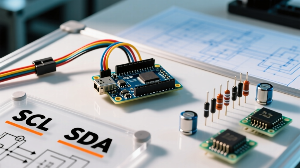
However, simply plugging SDA and SCL pins into an Arduino Uno R3 or ESP32 does not guarantee communication. True I2C compatibility relies on strict adherence to bus capacitance limits, proper pull-up resistor sizing, and meticulous logic-level translation. This guide provides a deep-dive compatibility matrix and hardware design framework for building robust I2C networks in 2026.
Core Hardware Constraints: The 400pF Capacitance Limit
The most common point of failure in complex Arduino projects is ignoring the physical layer limitations of the I2C bus. According to the official NXP I2C-bus specification (UM10204), the standard maximum allowable bus capacitance is 400 pF. This capacitance is cumulative, comprising the pin capacitance of the microcontroller, the trace capacitance on your PCB or breadboard, and the input capacitance of every slave device attached to the bus.
When you exceed 400 pF, the RC time constant of the bus increases. Because I2C relies on external pull-up resistors to drive the lines high, excessive capacitance causes the rising edge of the SDA and SCL signals to slope gently rather than snapping to a crisp digital HIGH. The Arduino's Wire library will interpret these slow rises as logic errors, resulting in corrupted data or complete bus lockups.
Calculating Pull-Up Resistor Values
To combat capacitance and ensure fast rise times, you must select the correct pull-up resistors. The standard 4.7kΩ resistor included on most cheap sensor breakouts is only optimal for 100kHz (Standard Mode) on short, 5V buses. For 400kHz (Fast Mode) or 3.3V logic, you must calculate the minimum and maximum resistor bounds.
The minimum resistor value is dictated by the maximum sink current ($I_{ol}$) of the devices, typically 3mA. The formula is $R_{p(min)} = (V_{cc} - V_{ol}) / I_{ol}$. For a 5V system, assuming a 0.4V voltage drop, the absolute minimum resistor is roughly 1.5kΩ. Using a resistor lower than this will fry the open-drain MOSFETs inside your sensors.
| Bus Voltage (Vcc) | Speed (Frequency) | Bus Length / Capacitance | Recommended Pull-Up |
|---|---|---|---|
| 5.0V | 100 kHz (Standard) | < 10cm / < 100pF | 4.7 kΩ |
| 5.0V | 400 kHz (Fast) | < 30cm / < 200pF | 2.2 kΩ |
| 3.3V | 100 kHz (Standard) | < 10cm / < 100pF | 3.3 kΩ |
| 3.3V | 400 kHz (Fast) | < 30cm / < 200pF | 1.5 kΩ to 2.2 kΩ |
Source: Adapted from Texas Instruments Application Note SLVA689 on I2C pull-up resistor sizing.
Logic Level Shifting: 5V vs 3.3V Arduino Boards
A massive compatibility hurdle in modern maker spaces is the voltage divide between legacy 5V boards (Arduino Uno R3, Mega 2560) and modern 3.3V architectures (ESP32-S3, Nano 33 IoT, Raspberry Pi Pico). Connecting a 3.3V I2C sensor directly to a 5V Arduino without level shifting will degrade the sensor's lifespan or instantly destroy its internal silicon.
Do not rely on simple resistor voltage dividers for I2C. Because I2C is bidirectional and open-drain, a passive voltage divider will prevent the slave device from pulling the SDA line low enough to register a logic '0' on the 5V master.
The BSS138 MOSFET Solution
The industry standard for I2C level shifting is the bidirectional MOSFET translator circuit, popularized by Philips and utilizing N-channel MOSFETs like the BSS138 or BSS84. Breakout boards like the SparkFun Logic Level Converter (BOB-12009) or Adafruit 4-channel I2C-safe Bi-directional Logic Level Converter (757) implement this topology. They isolate the 5V and 3.3V domains while allowing both sides to pull the bus to their respective ground potentials safely.
Expert Warning: If you are using an ESP32, remember that its I2C pins are software-mappable, but its native I2C hardware implementation has known errata regarding clock stretching. Always use the latest ESP32 Arduino Core (v3.x or newer) to ensure software-based I2C fallbacks are properly handled when interacting with sensors like the BME680 that hold the SCL line low during ADC conversions.
Common Sensor Compatibility & Address Matrix
I2C relies on 7-bit addressing, meaning you can theoretically connect 127 devices to a single Arduino. In reality, address collisions are a primary source of incompatibility. Below is a matrix of highly popular sensors, their default hex addresses, and hardware modification methods to resolve conflicts.
| Sensor / Module | Default I2C Address | Alternative Address | How to Change Address |
|---|---|---|---|
| BME280 (Bosch) | 0x76 | 0x77 | Bridge SDO pad to VCC (or cut trace on clones) |
| MPU6050 (InvenSense) | 0x68 | 0x69 | Pull AD0 pin HIGH |
| SSD1306 (128x64 OLED) | 0x3C | 0x3D | Move 0-ohm resistor on the back of the PCB |
| INA219 (Current Sensor) | 0x40 | 0x41, 0x44, 0x45 | Bridge A0/A1 address pads with solder |
| VL53L0X (Time-of-Flight) | 0x29 | Software configurable | Use XSHUT pin to boot sequentially and assign via Wire |
Troubleshooting I2C Lockups and NACK Errors
When your Arduino sketch hangs on Wire.endTransmission() or returns a NACK (Not Acknowledged) error, the issue is rarely in the code itself. It is almost always a physical layer incompatibility. Use the following diagnostic framework to isolate the failure mode.
1. The 'Bus Locked Low' Failure Mode
If the Arduino is reset or loses power while a slave device is actively transmitting a '0' (holding SDA low), the slave will continue holding the line low upon reboot, waiting for clock pulses that never come. The Arduino master will see a permanently low SDA line and refuse to initialize the Wire library.
Fix: Send 9 dummy clock pulses on the SCL line via software GPIO toggling before calling Wire.begin(). This allows the slave to finish its byte and release the SDA line.
2. Missing Common Ground
I2C is a single-ended protocol referenced to ground. If you are powering a sensor from a separate bench power supply and only connecting SDA, SCL, and VCC, the bus will fail. The voltage levels are meaningless without a shared ground reference.
Fix: Always run a dedicated GND wire alongside your SDA and SCL lines, keeping them twisted or routed closely together to minimize inductive loop area and EMI susceptibility.
3. SDA and SCL Swapped
Unlike UART, swapping SDA and SCL will not damage the hardware, but it will result in total silence. Silkscreen errors on cheap clone boards are notoriously common.
Fix: Run the standard i2c_scanner sketch. If it returns no devices, physically swap the SDA and SCL wires at the breadboard and run it again.
Summary Checklist for Reliable I2C Networks
- Verify Voltage: Confirm if your Arduino board operates at 5V or 3.3V. Use a BSS138 level shifter if mixing domains.
- Measure Capacitance: Keep bus wires under 30cm. For longer runs, use an active I2C bus extender like the PCA9600 or PCA9615.
- Check Pull-Ups: Ensure exactly one set of pull-up resistors exists on the bus. Multiple sensor breakouts with onboard 4.7kΩ resistors in parallel will drop the resistance too low, exceeding the 3mA sink limit.
- Scan Before Coding: Always run an I2C scanner sketch to verify hex addresses before integrating complex third-party libraries.
- Twist Your Wires: For off-board sensors, twist SDA and SCL together with a shared ground to reject common-mode noise from nearby motors or relays.
By moving past the '12c' typo and treating I2C as a rigorous analog-digital hybrid interface, you can eliminate the phantom lockups and data corruption that plague intermediate Arduino projects. Whether you are wiring a single OLED or daisy-chaining a dozen environmental sensors, respecting bus capacitance and logic thresholds is the key to bulletproof compatibility.