
The Economics and Engineering of DIY Pager Systems
Commercial restaurant and workshop paging systems typically rely on proprietary 433MHz or 900MHz FSK transceivers, costing between $45 and $65 per individual pager unit in 2026. For makers, hackspaces, or small business owners, building a custom pager Arduino network using off-the-shelf 2.4GHz RF modules reduces the per-node cost to under $9.00 while offering complete control over the communication protocol, payload encryption, and integration with existing IoT dashboards.
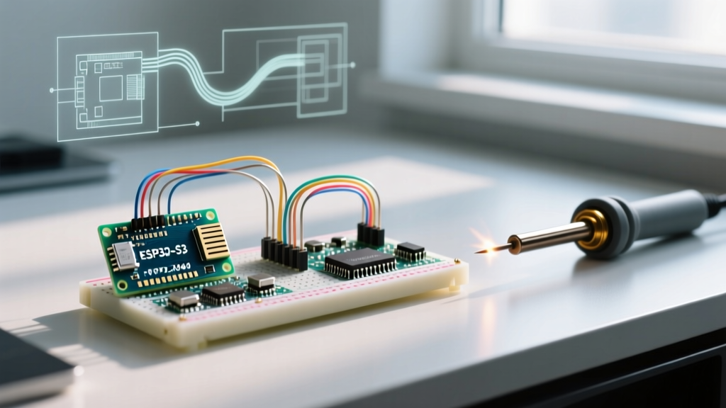
This configuration guide focuses on building a robust, low-power pager node using the ATmega328P and the highly ubiquitous Nordic Semiconductor nRF24L01+ transceiver. We will cover the exact SPI wiring matrices, RF24 library parameter tuning for maximum indoor range, and the critical deep-sleep configurations required to achieve multi-month battery life on a standard CR2032 coin cell.
Hardware Bill of Materials (BOM) & 2026 Cost Analysis
To maintain a low profile and eliminate the need for 5V-to-3.3V logic level shifters, the pager nodes must be built on the 3.3V/8MHz variant of the Arduino Pro Mini. Using a 5V Nano or Uno for the pager nodes will result in excessive quiescent current draw and potential destruction of the RF module's SPI pins.
| Component | Specification | Est. 2026 Cost | Role in Pager Node |
|---|---|---|---|
| Microcontroller | Arduino Pro Mini (3.3V / 8MHz) | $3.50 | Core logic, SPI master, sleep management |
| RF Transceiver | nRF24L01+ (Standard SMD antenna) | $1.80 | 2.4GHz ISM band communication |
| Haptic Alert | 1027 DC 3V Coin Vibration Motor | $0.85 | Silent tactile notification |
| Motor Driver | BC547 NPN BJT + 1kΩ Resistor + 1N4148 | $0.25 | Current amplification & flyback protection |
| Power Source | CR2032 Coin Cell + SMD Holder | $1.20 | Primary power (220mAh capacity) |
| Decoupling | 47µF Electrolytic Capacitor (6.3V) | $0.15 | TX burst current buffering |
Note: The base station (Transmitter) can utilize an Arduino Nano or ESP32, paired with an nRF24L01+ PA+LNA module ($4.50) to ensure blanket coverage across a multi-room floor plan.
SPI Wiring Matrix for the 3.3V Pager Node
The nRF24L01+ communicates via the SPI bus. Because we are using the 3.3V Pro Mini, the logic levels natively match the transceiver's requirements, preventing the common failure mode of fried SI/CE pins. Below is the strict pin mapping required for the standard RF24 library by TMRh20.
| nRF24L01+ Pin | Pro Mini (3.3V) Pin | Function |
|---|---|---|
| VCC | VCC (3.3V) | Power (1.9V to 3.6V tolerant) |
| GND | GND | Common Ground |
| CE | D9 | Chip Enable (RX/TX mode select) |
| CSN | D10 | Chip Select Not (SPI Slave select) |
| SCK | D13 | SPI Clock |
| MOSI | D11 | Master Out Slave In |
| MISO | D12 | Master In Slave Out |
Critical Engineering Note: The nRF24L01+ draws up to 115mA in short bursts during transmission. The onboard 3.3V regulator of cheap clone Pro Minis often cannot supply this transient current, leading to brownouts and SPI bus lockups. You MUST solder a 47µF electrolytic capacitor directly across the VCC and GND pins of the RF module to act as a local energy reservoir.
RF24 Library Configuration Parameters
Out-of-the-box examples for the SparkFun nRF24L01+ modules often use default settings that are highly susceptible to interference from 2.4GHz Wi-Fi routers and Bluetooth devices. To configure a reliable pager Arduino network, you must explicitly define the channel, data rate, and PA level in your initialization routine.
- Channel Selection: Use
radio.setChannel(108);. This sets the operating frequency to 2.508 GHz, completely bypassing the standard Wi-Fi channels (1, 6, and 11) which cluster between 2.412 GHz and 2.462 GHz. - Data Rate: Use
radio.setDataRate(RF24_250KBPS);. Dropping from the default 1Mbps to 250kbps increases the receiver sensitivity by roughly 6dB, effectively doubling the indoor range through drywall and timber framing. - PA Level: For the pager nodes (receivers), set
radio.setPALevel(RF24_PA_MIN);. The Power Amplifier level only affects transmission. Since the pagers only need to receive (and send brief ACKs), keeping the PA level at minimum drastically reduces current consumption.
Addressing and Payload Routing
A robust pager system requires both multicast (page all) and unicast (page specific table) capabilities. The nRF24L01+ supports up to 6 data pipes, but for a scalable network, we use a single pipe and embed the target ID in the payload struct.
struct PagerPayload {
  uint8_t targetID;   // 0 = All Pagers, 1-255 = Specific Pager
  uint8_t command;    // 1 = Vibrate, 2 = Clear, 3 = Battery Check
  uint16_t checksum;  // CRC validation
};
By configuring the base station to broadcast to a shared multicast address (e.g., 0xE8E8F0F0E1LL), all pagers wake up, read the targetID, and immediately return to sleep if the ID does not match their hardcoded EEPROM value. This prevents the need for the base station to manage complex routing tables.
Deep Sleep Configuration for Multi-Month Battery Life
The most challenging aspect of a pager Arduino build is power management. A standard CR2032 coin cell has a capacity of ~220mAh. If the Arduino and RF module remain in idle listening mode, they will draw ~15mA, draining the battery in less than 15 hours. We must utilize the ATmega328P's hardware sleep modes.
According to the official Arduino Low Power documentation, the powerDown mode disables the CPU, ADC, and SPI peripherals. Using the LowPower library by Rocket Scream, we can configure the pager to sleep in 8-second intervals.
#include <LowPower.h>
#include <RF24.h>

void enterDeepSleep() {
  radio.powerDown(); // Puts nRF24L01+ into 900nA sleep mode
  // Sleep for 8 seconds, ADC and BOD disabled
  LowPower.powerDown(SLEEP_8S, ADC_OFF, BOD_OFF);
  radio.powerUp();   // Wake RF module (requires 5ms settling time)
}
The 8-Second Polling Compromise
Waking up every 8 seconds to listen for a 5ms preamble introduces a maximum latency of 8 seconds between the base station sending a page and the pager vibrating. For restaurant or workshop environments, an 8-second delay is generally acceptable. If lower latency is required, the base station must transmit a continuous "wake-up burst" lasting 8.5 seconds to guarantee it overlaps with the pager's sleep window, which heavily congests the RF spectrum.
Driving the Vibration Motor Safely
A common beginner mistake is wiring a 3V coin vibration motor directly to an Arduino digital pin. These motors have a stall current of up to 90mA. The ATmega328P GPIO pins have an absolute maximum rating of 40mA, and continuous draws above 20mA will degrade the silicon and eventually destroy the port register.
The Correct Driver Circuit:
- Connect the motor's positive terminal to the 3.3V VCC rail.
- Connect the motor's negative terminal to the Collector of a BC547 NPN transistor.
- Connect the Emitter to GND.
- Place a 1kΩ resistor between the Arduino PWM pin (e.g., D5) and the Base of the transistor to limit base current to ~2.6mA.
- Solder a 1N4148 flyback diode in reverse parallel across the motor terminals (Cathode to VCC, Anode to Collector) to suppress inductive voltage spikes when the motor shuts off.
Edge Cases and Troubleshooting Failure Modes
When deploying a fleet of DIY pager Arduino nodes, you will inevitably encounter environmental and hardware edge cases. Below is a diagnostic matrix for the most frequent failure modes.
| Failure Symptom | Root Cause Analysis | Configuration / Hardware Fix |
|---|---|---|
| Pager receives first message, then permanently ignores subsequent pages. | SPI bus lockup caused by VCC brownout during the ACK transmission burst. | Install the 47µF decoupling capacitor. Add radio.flush_tx(); in the loop to clear hung FIFO buffers. |
| Range drops from 30 meters to 2 meters when held in the hand. | Multipath fading and body-block attenuation of the 2.4GHz PCB trace antenna. | Configure the base station to enable auto-acknowledgment retries: radio.setRetries(15, 15); to push through intermittent packet loss. |
| Battery drains in 3 weeks instead of 6 months. | Brown-Out Detection (BOD) remains active during sleep, drawing ~20µA continuously. | Use an ISP programmer (USBasp) to burn custom fuses, physically disabling the BOD hardware circuit on the ATmega328P. |
Final Integration Notes
Configuring a custom pager Arduino network bridges the gap between embedded systems theory and practical, high-utility deployment. By strictly adhering to the 3.3V logic requirements, optimizing the RF24 data rates for receiver sensitivity, and implementing rigorous hardware sleep states, you can deploy a fleet of pagers that rival commercial equivalents in reliability while retaining full ownership of the underlying firmware and network topology. Always ensure your 2.4GHz transmissions comply with local ISM band power output regulations, keeping the EIRP within legal limits for unlicensed operation.