
The Reality of MicroPython on Arduino Hardware
When makers search for a MicroPython Arduino workflow, they frequently hit a wall of conflicting documentation, bootloader traps, and pin-mapping nightmares. Unlike the seamless C++ compilation of the Arduino IDE, deploying MicroPython requires a fundamental shift in how you interact with the microcontroller's flash memory, USB CDC interfaces, and hardware abstraction layers.
As of 2026, the intersection of Arduino-branded hardware and MicroPython is dominated by 32-bit architectures. This guide bypasses generic advice and dives deep into the exact failure modes, baud-rate collisions, and memory fragmentation errors that plague developers working with the Arduino Nano RP2040 Connect (ABX00052), the Portenta H7, and the broader ESP32 ecosystem heavily utilized in Arduino-style maker workflows.
Critical Hardware Distinction: Classic 8-bit AVR boards (Uno R3, Nano, Mega 2560) do NOT support MicroPython. The ATmega328P possesses only 2KB of SRAM, whereas MicroPython requires a minimum of 16KB (and practically 64KB+ for stable REPL operations). This troubleshooting guide focuses exclusively on supported 32-bit ARM Cortex and Xtensa architectures.
Top 4 MicroPython Arduino Troubleshooting Scenarios
1. The "Dead Board" Bootloader Trap (Nano RP2040 Connect)
The most frequent panic-inducing issue for Arduino RP2040 users is the board vanishing from the Thonny IDE or OS device manager after a faulty script causes a hard fault or USB stack crash. Because the RP2040 lacks a dedicated hardware reset button on the Nano Connect footprint, users often assume the silicon is bricked.
The Fix: You must force the ROM bootloader into USB Mass Storage (UF2) mode.
- Method A (Software): If the board is still enumerating but unresponsive, use the IDE's "Stop/Restart" backend command to interrupt the boot sequence before
main.pyexecutes. - Method B (Hardware Jumper): The Nano RP2040 Connect does not have a physical BOOTSEL button. Instead, locate the REC (Recovery) pin pad on the bottom of the PCB. Bridge the REC pad to GND using a jumper wire, then plug in the USB-C cable. The board will mount as a
RPI-RP2USB drive. Drag and drop the latestmicropython-rp2-pico-w(or standard pico).uf2file directly onto the root directory.
For comprehensive hardware schematics and pad locations, refer to the Arduino Nano RP2040 Connect Technical Reference.
2. ESP32 Flash Timeout & Baud Rate Collisions
While not branded by Arduino, ESP32-WROOM-32 boards are the backbone of Arduino-ecosystem IoT projects. When flashing MicroPython via esptool.py, users frequently encounter Timed out waiting for packet header or Invalid head of packet (0x00) errors.
The Root Cause: Many third-party ESP32 clones utilize the CH340G USB-to-UART bridge instead of the CP2102. The CH340G struggles to maintain stable data framing at the default esptool baud rate of 460800, leading to buffer overruns and flash write corruption.
The Fix: Manually throttle the baud rate and specify the exact flash address. Open your terminal and execute:
esptool.py --chip esp32 --port /dev/ttyUSB0 --baud 115200 write_flash -z 0x1000 esp32-idf4-20231227-v1.22.1.binDropping the baud rate to 115200 adds roughly 12 seconds to the flash time but guarantees a 99.9% success rate on CH340-equipped boards. For deeper ESP32 firmware management, consult the Official MicroPython ESP32 Documentation.
3. Pin Mapping Nightmares (Arduino IDE vs. MicroPython)
A massive point of friction occurs when developers port code from the Arduino IDE to MicroPython. The Arduino IDE uses an abstraction layer mapped to silk-screen labels (e.g., D2, A0). MicroPython bypasses this abstraction and addresses the raw silicon GPIO pins. If you attempt to use Pin('D2') in MicroPython on an Arduino-branded board, the interpreter will throw a ValueError or silently map to the wrong internal trace.
Arduino Nano RP2040 Connect Pin Translation Matrix
| Arduino Silk Screen | MicroPython GPIO | Hardware Peripheral | Common Failure Mode |
|---|---|---|---|
| D2 | GPIO26 | ADC0 / I2C | Using digital read on an active ADC channel without disabling pull-downs. |
| D4 | GPIO28 | ADC2 | Conflict with internal WiFi/BLE module traces if not isolated. |
| D11 (SPI COPI) | GPIO7 | SPI0 TX | Attempting to use software SPI instead of hardware SPI0 bus. |
| D12 (SPI CIPO) | GPIO4 | SPI0 RX | Missing external pull-up resistor on MISO line causing floating states. |
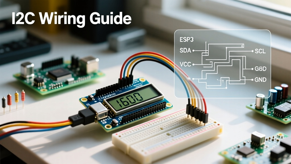
| A4 (SDA) | GPIO12 | I2C0 SDA | Confusing I2C0 with I2C1 (GPIO6/7) which is routed to the onboard IMU. |
Pro Tip: Always initialize your I2C bus using the explicit GPIO integers rather than string aliases. For example, use i2c = I2C(0, scl=Pin(13), sda=Pin(12), freq=400000) to ensure you are targeting the external header pins and not the internal Nina-W102 WiFi module bus.
4. MemoryError on Resource-Constrained MCUs
MicroPython is a garbage-collected language. When running continuous sensor-logging loops or handling MQTT payloads on boards with limited SRAM (like the 264KB on the RP2040 or 520KB on the ESP32), you will inevitably hit a MemoryError: memory allocation failed. This rarely means you are out of total RAM; it means your heap is heavily fragmented, and the interpreter cannot find a contiguous block of memory for a new object.
The Fix: Implement aggressive memory management protocols in your main.py.
- Manual Garbage Collection: Insert
gc.collect()at the end of every major loop iteration. Check free memory usinggc.mem_free(). - Pre-allocate Bytearrays: Never use string concatenation (
+=) to build JSON payloads or data buffers. This creates a new object in memory on every append. Instead, pre-allocate abytearrayand use memoryview slicing. - Heap Locking: For time-critical interrupt service routines (ISRs), use
micropython.heap_lock()to prevent the garbage collector from running mid-interrupt, which causes severe timing jitter and hard faults.
Step-by-Step Firmware Rescue Flowchart
When a board becomes entirely unresponsive and standard REPL access fails, follow this exact diagnostic sequence using the Thonny IDE:
- Disconnect USB: Unplug the board and wait 10 seconds for capacitors to discharge.
- Enter Safe Mode: For RP2040 boards, bridge the REC/BOOTSEL pins. For ESP32, hold the BOOT button on the PCB.
- Reconnect & Verify Enumeration: Plug in the USB cable. Check your OS device manager for a new COM port or Mass Storage Device.
- Wipe the Filesystem: If mounted as a drive, delete
main.pyandboot.pyto prevent auto-execution of faulty code upon reboot. - Flash Factory Firmware: Use the IDE's "Install MicroPython" dialog to overwrite the flash partition table completely, ensuring no corrupted C-code modules remain in the frozen bytecode sector.
Frequently Asked Questions
Can I use the Arduino IDE to write MicroPython code?
No. The Arduino IDE is strictly a C/C++ compiler built around the GCC toolchain and avr-dude/esptool wrappers. To write MicroPython, you must use a dedicated IDE like Thonny, Mu Editor, or VS Code with the MicroPico extension. The Arduino IDE is only useful for generating the initial C++ bootloader or WiFi firmware blobs that MicroPython relies on.
Why does my Arduino Portenta H7 crash when importing machine modules?
The Portenta H7 features a dual-core architecture (Cortex-M7 and Cortex-M4). MicroPython primarily runs on the M7 core. If you attempt to initialize hardware peripherals that are strictly routed to the M4 core or the FPGA fabric without proper inter-processor communication (IPC) setup via the openamp library, the M7 core will trigger a HardFault exception. Always verify peripheral bus ownership in the STM32H747 datasheet before initializing pins.
How do I persist data across reboots without wearing out the flash?
Flash memory on RP2040 and ESP32 chips has a limited write endurance (typically 10,000 to 100,000 cycles). Do not use standard file I/O (open('data.txt', 'w')) for high-frequency logging. Instead, utilize the board's onboard EEPROM emulation or an external I2C FRAM (Ferroelectric RAM) chip like the MB85RC256V, which supports 10^14 read/write cycles and interfaces seamlessly with MicroPython's I2C bus.