
The Ultimate Quick-Reference Guide to Arduino Photoresistor Circuits
Photoresistors, also known as Light Dependent Resistors (LDRs) or photocells, are foundational components in maker projects. Whether you are building an automated night light, a solar tracker, or a laser tripwire, understanding the core mechanics of an Arduino photoresistor circuit is essential. This FAQ and quick-reference guide cuts through the fluff, providing exact hardware specifications, voltage divider math, and advanced troubleshooting techniques for modern microcontroller environments in 2026.
Component Quick-Reference: Selecting the Right LDR
Not all photoresistors are created equal. Choosing the wrong model for your ambient light conditions will result in a compressed analog reading range. Below is a comparison of the most common LDRs and phototransistors available on the market today.
| Component Model | Type | Dark Resistance (Min) | Illuminated Resistance (10 Lux) | Response Time | Approx. 2026 Price |
|---|---|---|---|---|---|
| GL5528 | CdS LDR | 1 MΩ | 10 kΩ - 20 kΩ | 20 - 30 ms | $0.08 - $0.12 |
| GL5516 | CdS LDR | 0.5 MΩ | 5 kΩ - 10 kΩ | 20 - 30 ms | $0.08 - $0.12 |
| GL5539 | CdS LDR | 5 MΩ | 50 kΩ - 100 kΩ | 30 - 50 ms | $0.10 - $0.15 |
| TEMT6000 | Phototransistor | N/A (Leakage ~10nA) | N/A (Current based) | < 15 µs | $1.20 - $1.50 |
Expert Insight: If your project requires detecting high-speed light changes (like a tachometer or optical encoder), abandon CdS photoresistors entirely. Their 20ms+ response time is too slow. Use a TEMT6000 phototransistor or a dedicated photodiode instead.
Hardware & Wiring FAQ
How do I wire an Arduino photoresistor circuit?
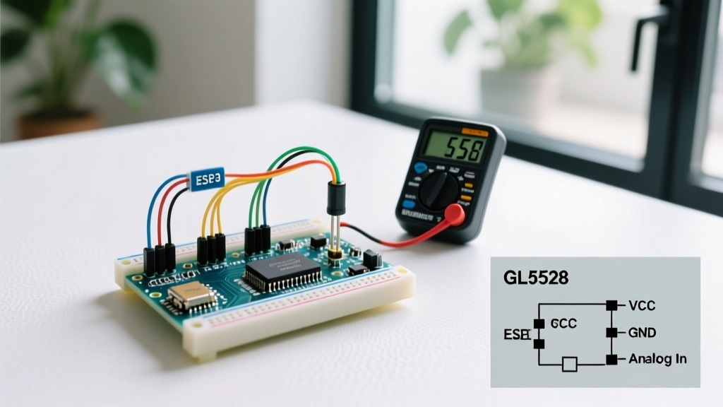
Microcontrollers cannot read resistance directly; they read voltage. Therefore, you must wire the LDR as part of a voltage divider. According to SparkFun's Voltage Divider Guide, this requires two resistors in series between VCC and GND.
- Connect one leg of the GL5528 LDR to the 5V (or 3.3V) pin.
- Connect the other leg of the LDR to an analog input pin (e.g., A0).
- Connect a fixed 'pull-down' resistor (typically 10kΩ) between that same analog pin (A0) and GND.
Does the polarity of the photoresistor matter?
No. Standard Cadmium Sulfide (CdS) photoresistors are passive, non-polarized components. You can wire them in either direction without affecting performance or risking damage to the component.
How do I calculate the optimal pull-down resistor value?
Many beginners blindly use a 10kΩ resistor, but this is only optimal if the LDR's resistance at your target light level is also around 10kΩ. To maximize the analog voltage swing, the fixed resistor ($R_{fixed}$) should ideally equal the geometric mean of the LDR's minimum and maximum expected resistances:
R_fixed = √(R_dark × R_light)
For a GL5528 in a typical indoor room (ranging from 5kΩ in bright light to 200kΩ in dim shadows): √(5,000 × 200,000) = 31,622Ω. In this specific indoor scenario, a 33kΩ pull-down resistor will yield a much wider and more usable analog range than the standard 10kΩ.
Code & Calibration FAQ
How do I read and map the analog values?
The Arduino analogRead() function queries the Analog-to-Digital Converter (ADC). However, you must account for the specific architecture of your board. As of 2026, the Arduino Uno R4 Minima is the standard baseline, featuring a 14-bit ADC, unlike the legacy 10-bit ADC on the Uno R3.
- Uno R3 / Nano (10-bit): Returns values from 0 to 1023.
- Uno R4 / ESP32 (12 to 14-bit): Returns values up to 4095 or 16383.
Always use the map() function to translate raw ADC readings into actionable percentages or lux estimations:
int rawValue = analogRead(A0);
// For Uno R4 (14-bit resolution)
int lightPercent = map(rawValue, 0, 16383, 0, 100);
Why are my readings inverted? (Dark = High, Light = Low)
This is dictated by your physical wiring topology. If the LDR is connected to VCC and the fixed resistor is connected to GND, voltage at the analog pin increases as light increases. If you swap them (LDR to GND, fixed resistor to VCC), the logic inverts. If you cannot rewire the board, simply invert the reading in software: int invertedValue = 1023 - rawValue; (adjust 1023 to 16383 for 14-bit boards).
Troubleshooting & Edge Cases
Problem: The serial monitor only prints 1023 (or 16383) or only 0.
Cause: You have a floating pin or a short circuit.
- If stuck at MAX: The analog pin is reading full VCC. Check if the pull-down resistor to GND is missing, broken, or if the LDR is shorted internally.
- If stuck at 0: The analog pin is reading GND. Check if the LDR is disconnected from VCC, or if the pull-down resistor is accidentally bridging the analog pin directly to GND without the LDR in the circuit.
Problem: The readings are jittery and fluctuate wildly.
Cause: Electromagnetic interference (EMI), long unshielded wires, or mains-powered light flicker.
According to Adafruit's Photocell Tutorial, LDRs are highly susceptible to environmental noise. Fluorescent bulbs and cheap LED drivers flicker at 100Hz or 120Hz (twice the AC mains frequency). If your ADC sampling rate aliases with this flicker, your readings will bounce.
The Hardware Fix: Add a 0.1µF ceramic capacitor in parallel with the fixed pull-down resistor. This creates a hardware low-pass RC filter, smoothing out high-frequency mains flicker.
The Software Fix: Implement a moving average filter or oversampling. Taking 16 rapid samples, averaging them, and bit-shifting is a highly effective way to stabilize LDR data without introducing the latency of a physical capacitor.
Problem: The LDR response is too slow when a shadow passes over it.
Cause: The 'Dark Recovery Time' of CdS cells is inherently slow. Furthermore, if you added a large capacitor to fix jitter (e.g., 10µF), you have created an RC time constant that physically prevents the voltage from changing quickly. Reduce the capacitor value to 0.01µF or rely entirely on software oversampling to maintain fast transient response.
Summary Checklist for 2026 Builds
- Verify your microcontroller's ADC resolution (10-bit vs 12/14-bit) before hardcoding
map()limits. - Calculate the geometric mean of your expected light/dark resistance to choose the perfect pull-down resistor.
- Use a 0.1µF capacitor across the pull-down resistor if operating under artificial AC lighting.
- Upgrade to a TEMT6000 phototransistor if your application requires sub-millisecond response times.