
Introduction to the Mega Board Arduino Ecosystem
When your project outgrows the 14 digital I/O pins and 32 KB flash memory of the standard Uno, upgrading to a mega board arduino is the logical next step. Built around the Microchip ATmega2560 microcontroller, this powerhouse offers 54 digital I/O pins, 16 analog inputs, and a massive 256 KB of flash memory. However, simply plugging it in and hitting 'Upload' is rarely enough for complex robotics, multi-sensor environmental stations, or large LED matrices. Proper configuration of the IDE, power delivery, and peripheral buses is critical to prevent silent failures, memory overflows, and thermal throttling.
This comprehensive configuration guide will walk you through the exact IDE settings, hardware silicon differences, power management limits, and advanced peripheral routing required to get the most out of your Mega 2560 in 2026.
Initial IDE Configuration & Board Selection
The Arduino IDE (both the legacy 1.8.x and the modern 2.x series) requires specific board definitions to compile code correctly for the ATmega2560's memory architecture. Unlike the ATmega328P, the Mega utilizes a 16-bit program counter, which changes how the compiler handles memory addressing and bootloader handoffs.
- Board Manager Installation: Open the Boards Manager and ensure you have the latest Arduino AVR Boards package installed (version 1.8.6 or newer is recommended for optimal avr-gcc compiler optimizations).
- Board Selection: Navigate to Tools > Board and select Arduino Mega or Mega 2560.
- Processor Configuration: Under Tools > Processor, ensure ATmega2560 (Mega 2560) is selected. Selecting the legacy ATmega1280 will result in immediate memory overflow errors during compilation.
- Programmer Setting: For standard USB uploads, the programmer should be set to AVRISP mkII. If you are using an external ISP programmer to burn a fresh bootloader, switch this to USBasp or Arduino as ISP.
Official vs. Clone: Silicon & Driver Configuration
As of 2026, an official Arduino Mega 2560 Rev3 retails for approximately $48.00, while high-quality third-party clones (from brands like Elegoo or HiLetgo) can be sourced for $14.00 to $18.00. The configuration of the USB-to-Serial bridge is the primary difference between them.
- Official Rev3: Uses a dedicated ATmega16U2 microcontroller programmed as a USB-to-Serial converter. This chip supports native HID (Human Interface Device) configurations, allowing the Mega to emulate a keyboard or mouse without external libraries. It uses native OS drivers on Windows, macOS, and Linux.
- Third-Party Clones: Almost universally utilize the CH340G or CH340C USB-to-Serial chip to cut costs. While highly reliable, the CH340 requires a specific driver installation on Windows (macOS and modern Linux kernels usually include it natively). Furthermore, clones lack the HID capabilities of the 16U2.
Configuration Tip: If your clone board is not showing up in the IDE's Port menu on Windows 11, download the latest CH340 signed driver directly from the WCH (Nanjing Qinheng) official repository. Avoid third-party driver aggregator sites.
Hardware Specifications & Pinout Mapping
Understanding the physical mapping of the ATmega2560 is crucial. Many makers assume the Mega is simply an 'extended Uno', but several critical pins have been relocated. Refer to the Arduino Mega 2560 Documentation for the official schematic, but keep this comparison matrix on hand during wiring.
| Feature | Arduino Uno (ATmega328P) | Mega Board Arduino (ATmega2560) |
|---|---|---|
| Flash Memory | 32 KB | 256 KB (8 KB used by bootloader) |
| SRAM | 2 KB | 8 KB |
| EEPROM | 1 KB | 4 KB |
| Digital I/O Pins | 14 (6 PWM) | 54 (15 PWM) |
| Hardware Serial Ports | 1 (Serial) | 4 (Serial, Serial1, Serial2, Serial3) |
| I2C Pins | A4 (SDA), A5 (SCL) | 20 (SDA), 21 (SCL) |
| SPI Pins | 11-13 | 50-52 (plus ICSP header) |
Note: The relocation of the I2C and SPI pins means that older shields designed strictly for the Uno will not automatically connect to the Mega's I2C/SPI buses without jumper wires or a dedicated Mega shield adapter.
Power Configuration & Thermal Limits
Power misconfiguration is the leading cause of dead Mega boards. The board features three distinct power input methods, each with strict thermal and current limits dictated by the onboard voltage regulator.
The Voltage Regulator Bottleneck
Official boards use an NCP1117-5.0 linear regulator, while most clones use an AMS1117-5.0. Both are linear regulators, meaning they dissipate excess voltage as heat. The power dissipated is calculated as: P = (Vin - 5V) × Current.
- USB Power (5V): Bypasses the regulator entirely. Limited by the USB port (typically 500mA for USB 2.0, 900mA for USB 3.0) and the board's polyfuse (rated at 500mA resettable).
- Vin Pin / Barrel Jack (7V - 12V): Passes through the linear regulator. If you supply 12V and draw 200mA from the 5V pin, the regulator must dissipate (12V - 5V) × 0.2A = 1.4 Watts. Without a heatsink, the SOT-223 package will hit thermal shutdown (around 150°C junction temperature) at roughly 800mA of continuous draw at 9V.
- Direct 5V Pin Injection: You can bypass the regulator entirely by feeding a regulated, clean 5V source directly into the '5V' pin. Warning: This bypasses the polyfuse and reverse-polarity protection. A voltage spike of 5.5V or higher can instantly destroy the ATmega2560 silicon.
Hardware Serial Port Configuration
One of the most powerful features of the mega board arduino is its four independent hardware UARTs. This allows you to communicate with a PC, a GPS module, a cellular modem, and an RS485 bus simultaneously without relying on the CPU-heavy SoftwareSerial library.
- Serial (Pins 0/1): Connected to the USB-to-Serial bridge. Used for IDE Serial Monitor and firmware uploads. Avoid using these pins for external peripherals unless you disconnect them during uploads.
- Serial1 (Pins 19 RX / 18 TX): Ideal for GPS modules (typically 9600 baud) or secondary telemetry.
- Serial2 (Pins 17 RX / 16 TX): Frequently configured for RS485 transceivers (like the MAX485) in industrial sensor networks.
- Serial3 (Pins 15 RX / 14 TX): Perfect for Bluetooth (HC-05) or Wi-Fi (ESP8266/ESP32) AT-command modules.
Configuration Code Snippet:
void setup() {
  Serial.begin(115200);  // USB Debugging
  Serial1.begin(9600);   // GPS Module
  Serial2.begin(115200); // ESP32 Bridge
}
Advanced I2C Bus Configuration & Edge Cases
The I2C bus on the Mega (Pins 20 and 21) has a specific hardware quirk that catches many advanced makers off guard. According to the Microchip ATmega2560 Datasheet, the internal pull-up resistors on the I2C lines are approximately 30kΩ to 50kΩ.
While this is sufficient for a single sensor on a short 5cm trace, it is entirely inadequate for complex configurations. If you are running an I2C multiplexer (like the TCA9548A), multiple OLED displays, or long wire runs, the parasitic capacitance of the wires will slow down the signal rise time, causing data corruption and 'hanging' code.
The Pull-Up Resistor Fix
As detailed in the SparkFun I2C Tutorial, you must disable the internal pull-ups (handled automatically by the Wire library in most cases) and add external pull-up resistors. For a standard 100kHz I2C bus on the Mega with 3-4 devices, solder 4.7kΩ resistors between the SDA line and 5V, and the SCL line and 5V. If you push the bus to 400kHz (Fast Mode), drop the resistors to 2.2kΩ.
Troubleshooting Bootloader & Upload Timeouts
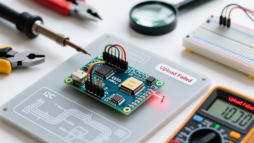
A frequent issue when configuring a new mega board arduino—especially clones—is encountering the dreaded avrdude: stk500v2_ReceiveMessage(): timeout error. This indicates the IDE cannot establish a handshake with the bootloader.
Root Causes and Solutions
- Missing Auto-Reset Capacitor: The official Mega uses a 0.1µF capacitor between the DTR line of the USB chip and the RESET pin of the ATmega2560. This capacitor creates a brief voltage spike that resets the board right before uploading. Many cheap clones omit this capacitor to save fractions of a cent.
- Software Fix: None. You must manually press and release the physical RESET button on the board the exact moment the IDE status bar changes from 'Compiling' to 'Uploading'.
- Hardware Fix: Solder a 0.1µF ceramic capacitor between the RST pin and the GND pin on the ICSP header, or directly across the reset switch.
- Corrupted Bootloader: If you previously used the board with an ISP programmer and didn't re-burn the bootloader, the fuses may have been altered. Use a USBasp programmer and select Tools > Burn Bootloader in the IDE to restore the factory configuration.
- USB Cable Data Lines: Ensure you are using a high-quality USB-B to USB-A (or USB-C) cable rated for data transfer. Many 2026 electronics kits still include charge-only cables that lack the internal D+ and D- data wires, resulting in a board that powers on but cannot be configured.
Conclusion
Configuring a mega board arduino requires moving beyond the plug-and-play mindset of simpler microcontrollers. By correctly managing your IDE board definitions, respecting the thermal limits of the linear voltage regulator, mapping your hardware serial ports efficiently, and properly terminating your I2C buses, you unlock the true potential of the ATmega2560. Whether you are building a multi-axis CNC controller or a sprawling home automation hub, these foundational configurations will ensure your project remains stable, responsive, and ready for scale.