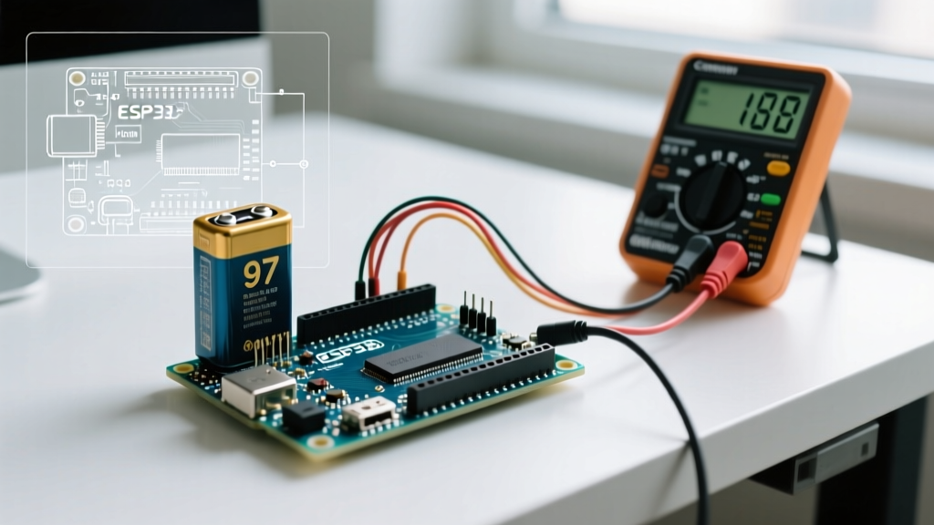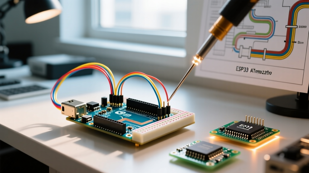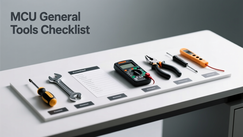
Every professional embedded systems engineer knows that reliable MCU development isn’t about the microcontroller alone—it’s about the ecosystem of tools that enable measurement, validation, debugging, and physical implementation. This checklist distills over a decade of lab experience across automotive, industrial, and IoT projects into a pragmatic, vendor-agnostic inventory. It covers tools used daily—not just for bring-up, but for diagnosing subtle timing violations (e.g., I²C clock stretch under 2.3 µs), validating power rail ripple (<15 mVpp at 100 kHz), or recovering from JTAG lockup on STM32H743 or nRF52840 devices. No theoretical wishlists: every item listed has been deployed in production firmware validation, ESD-sensitive environments, and high-density PCB rework scenarios.
Core Measurement Instruments
Accurate measurement is non-negotiable when validating analog sensor interfaces, verifying switching regulator stability, or characterizing GPIO toggle timing. Guesswork leads to field failures—especially when operating near datasheet limits.
Digital Multimeter (DMM)
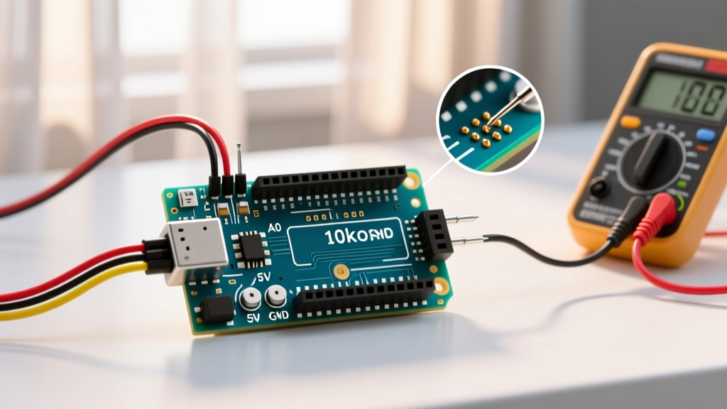
A true RMS DMM with 6½-digit resolution is essential for precision voltage, current, and continuity checks. The Keysight 34465A delivers 0.0035% basic DC voltage accuracy, 100 µA minimum current range with 10 pA resolution, and 10 MΩ input impedance—critical when measuring supply currents on ultra-low-power MCUs like the Silicon Labs EFM32PG23 (which draws 1.2 µA in EM4 sleep). Fluke’s 87V True RMS model remains widely trusted in field service for its 10 kV transient rating and CAT III 1000 V safety certification. Avoid generic USB-powered DMMs lacking isolation—they risk ground loops and lack certified safety margins.
Oscilloscope
For digital signal integrity and timing analysis, bandwidth and sample rate dictate what you can observe. A 1 GHz bandwidth scope with ≥5 GS/s real-time sampling is required for clean capture of SPI clock edges at 50 MHz (with >5× oversampling per Nyquist–Shannon). The Tektronix MSO58 offers 8 analog + 16 digital channels, 250 Mpts record length, and built-in serial protocol decode for UART, I²C, SPI, and CAN FD—enabling correlation between logic-level toggles and physical bus behavior. For budget-conscious teams, the Rigol DS1074Z (70 MHz, 1 GS/s) suffices for basic GPIO and UART verification on legacy 8-bit MCUs like the PIC18F45K22, but fails to resolve rise times <3.5 ns—common in modern ARM Cortex-M4/M7 peripherals.
Debug & Programming Hardware
Debug probes are the lifeline during bring-up and runtime analysis. Their reliability directly impacts firmware iteration speed—and their capabilities determine whether you can trace execution, inspect registers mid-interrupt, or recover bricked devices.
JTAG/SWD Debug Probes
The Segger J-Link PRO supports SWD/JTAG up to 12 MHz, full-speed RTT (Real-Time Transfer) logging, and flash programming for over 2,500 device families—including Infineon’s AURIX TC3xx and NXP’s i.MX RT1170. Its 100 Mbps USB 2.0 interface avoids bottlenecks during large RAM dumps. In contrast, the ST-LINK/V3SET (sold with STM32 Discovery kits) maxes out at 4 MHz SWD clock and lacks SWO trace support—making it unsuitable for deep profiling of FreeRTOS task switches on STM32F429. For open-source workflows, the Black Magic Probe v2.3 (based on STM32F103CB) provides GDB server integration without drivers and supports SWD on ARM Cortex-M0+/M3/M4/M7—but lacks hardware breakpoints beyond four and cannot program internal flash on Cypress PSoC6 devices due to proprietary security keys.
Always verify probe compatibility with your target’s debug interface voltage. The J-Link EDU Mini includes level-shifting down to 1.2 V, enabling safe connection to 1.8 V I/O domains on ESP32-S3 or RP2040 without external translators.
Logic Analyzers
While oscilloscopes show analog waveforms, logic analyzers capture precise digital timing across multiple signals simultaneously. The Saleae Logic Pro 16 supports up to 16 channels at 500 MS/s (2 ns resolution), with hardware-based triggering on complex state machines—critical for validating custom SPI slave implementations or decoding 1-Wire bus arbitration on Dallas DS18B20 sensors. For low-cost validation, the Siglent SDS1104X-E oscilloscope (100 MHz, 4 channels) includes optional 16-channel logic analyzer firmware (SLA1016), though its 100 MS/s sampling limit restricts visibility into sub-10 ns setup/hold violations common in parallel memory interfaces on older ATmega2560 designs.
Power Delivery & Regulation
Unstable power kills MCUs silently—causing brown-out resets, corrupted flash writes, or intermittent ADC offsets. A clean, controllable power source is foundational—not an afterthought.
Bench Power Supplies
Triple-output bench supplies with independent tracking and remote sensing are mandatory for multi-rail systems. The Keysight E36313A delivers three isolated outputs (±25 V, 6 V @ 10 A), 0.01% load regulation, and 2 mVpp ripple/noise—validated using a Rohde & Schwarz RTO2044 oscilloscope in 20 MHz bandwidth limit mode. Its 4-wire Kelvin sensing eliminates voltage drop errors in long test leads, ensuring ±6.000 V reaches the VDD pin of a TMS320F28379D DSP even with 1.2 m of 22 AWG wire. The less expensive Rigol DP832A (30 V/3 A ×3) exhibits 8 mVpp noise at 100 kHz and lacks remote sense—making it unsuitable for powering RF sections of Nordic nRF9160 SiP modules, where >5 mVpp ripple degrades LTE sensitivity by 3 dB.
Always use low-ESR bulk capacitors (e.g., 47 µF ×2, Panasonic SP-Cap POSCAP) at the MCU’s VDD pins—even when powered from a lab supply—to absorb high-frequency transients generated by synchronous rectifiers or motor drivers.
Soldering & Rework Stations
Modern MCUs often ship in QFN-48, WLCSP-64, or BGA-100 packages. Reliable assembly and repair demand precision thermal control—not brute-force heating.
Soldering Irons & Stations
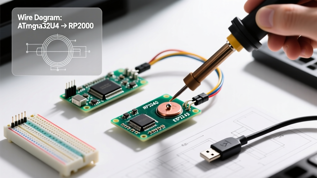
The JBC CD-2BE station with C245 cartridge delivers instant thermal recovery (≤2 seconds from 300 °C to 350 °C under load) and ±1 °C temperature stability—verified via Fluke 54II thermocouple calibration. Its 0.2 mm chisel tip handles 0.4 mm pitch QFN pads on NXP LPC55S69 without bridging. Cheaper Chinese clones (e.g., KSGER T12 variants) drift ±8 °C and exhibit 12-second recovery—leading to cold joints and lifted pads during rework of TI MSP430FR5994 FRAM devices.
Hot Air Rework Stations
The Quick 861DW features dual-zone heating (top nozzle + bottom preheat), adjustable airflow (10–60 L/min), and PID-controlled temperature (100–480 °C). Its 0.5 mm nozzle achieves 380 °C surface temperature on a 0.5 mm pitch BGA within 60 seconds—sufficient for removing Xilinx Zynq-7010 SoC packages without damaging adjacent 0402 decoupling capacitors. Avoid single-nozzle units lacking preheating; they cause PCB warping and tombstoning on 0201 passives near reworked ICs.
Firmware & Validation Utilities
Hardware tools mean little without software that extracts actionable insights from raw data.
Python-based utilities dominate modern workflows. PyOCD v2.32 supports CMSIS-DAP, ST-LINK, and J-Link probes, enabling automated flash verification scripts that compare SHA-256 hashes of .hex files against read-back memory contents—critical for ASIL-B automotive compliance. The open-source openocd 0.12.0 release adds native support for RISC-V debug on GD32VF103, but lacks secure boot key injection for STM32L552’s Secure Boot Manager—a gap filled only by ST’s STM32CubeProgrammer v2.16.0.
For bootloader development, the NXP MCUXpresso IDE v11.7.0 integrates a cycle-accurate simulator for S32K144, allowing interrupt latency testing without hardware. However, it cannot model external crystal startup delays—requiring actual board validation with a 100 MHz scope probe on the XTAL_OUT pin.
Essential Consumables & Accessories
Overlooked items often cause more downtime than faulty instruments. Here’s what belongs in every lab drawer:
- High-purity 63/37 tin-lead solder (Kester 24-6337-1122, 0.5 mm diameter) for prototyping—lower melting point (183 °C) reduces thermal stress on 0.3 mm thick PCBs
- Flux pens with ROL0 core (MG Chemicals 8331) for selective application—avoids residue-induced leakage current on high-impedance ADC inputs
- ESD-safe tweezers (Kai 7010-10, stainless steel, carbon-fiber anti-static coating) rated to <100 Ω resistance
- Microscope-compatible desoldering braid (Chemtronics CW800, 1.5 mm width, silver-plated copper) capable of wicking 0.2 mm pitch traces
- Calibrated torque screwdrivers (Wiha 26100, 0.5–5 cN·m range) for securing M2.5 mounting screws on Raspberry Pi Pico W without cracking the RP2040’s ceramic package
Never substitute isopropyl alcohol (IPA) for electronics cleaning unless it’s ≥99.9% pure (Electro-Wash PX from Chemtronics). 91% pharmacy-grade IPA leaves conductive residues that increase surface leakage by up to 200 nA on 10 MΩ pull-ups—enough to falsely trigger wake-on-pin interrupts on Microchip SAMD51.
Validation & Calibration Schedule
Tools degrade. Uncalibrated equipment produces false confidence. A documented schedule ensures traceability and regulatory readiness.
Per ISO/IEC 17025 requirements, DMMs and oscilloscopes require annual calibration against NIST-traceable standards. Keysight-certified labs perform full parameter validation—including AC voltage accuracy at 1 MHz (±0.5% for 34465A) and timebase stability (±1 ppm/year). Oscilloscope probe compensation must be verified before each use: connect the probe to the 1 kHz square wave cal output and adjust trimmer until overshoot <5% and rise time matches spec (e.g., ≤350 ps for Tektronix TPP1000).
Below is a summary of recommended calibration intervals and critical parameters:
| Tool | Critical Parameter | Calibration Interval | Max Allowed Drift | Verification Method |
|---|---|---|---|---|
| Keysight 34465A DMM | DC Voltage (10 V range) | 12 months | ±0.0035% | Fluke 732B DC Reference Standard (±0.0005%) |
| Tektronix MSO58 | Timebase Accuracy | 12 months | ±1 ppm | Rohde & Schwarz FSWP Phase Noise Analyzer |
| J-Link PRO | SWD Clock Timing | 24 months | ±5% | Oscilloscope measurement on SWCLK pin with 10:1 probe |
| Quick 861DW Hot Air | Nozzle Temperature | 6 months | ±5 °C | Omega HH506DK Thermocouple Meter (Type K, ±0.5 °C) |
| Keysight E36313A PSU | Load Regulation (6 V @ 5 A) | 12 months | ±0.01% | Keysight 34465A + 0.1 Ω/50 W shunt resistor |
Calibration certificates must include as-found/as-left data, uncertainty budgets, and technician signatures. Internal verification logs should record date, tool ID, operator, and pass/fail status—stored for minimum seven years per IATF 16949 clause 7.1.5.2.
What to Exclude (and Why)
Not every shiny tool belongs in your workflow. Some introduce more risk than value:
- USB-to-Serial Adapters with CH340G chips: Lack proper hardware flow control and exhibit 12–18 ms transmit latency—unacceptable for real-time UART-based OTA updates on ESP32-WROVER modules requiring <5 ms round-trip response.
- Non-isolated oscilloscope probes: Connecting a standard 10× passive probe (e.g., Tektronix TPP0250) to a 400 VDC bus without differential isolation risks catastrophic ground loop currents (>100 A) through the scope’s chassis—destroying both probe and instrument.
- Generic ‘programmer’ boards labeled ‘STM32 Compatible’: Often omit the BOOT0/BOOT1 pin pull-up resistors required for system memory boot mode on STM32F030, leading to failed DFU recovery attempts.
- Lead-free solder pastes below 230 °C reflow: Fail to fully wet OSP-coated pads on J-Link OB debug headers, causing intermittent SWD connections that mimic faulty firmware.
Finally, never skip environmental controls. Ambient humidity above 60% RH accelerates dendritic growth between 0.25 mm pitch QFP pins on Renesas RA6M4—causing latent shorts that manifest only after 72 hours of thermal cycling. Maintain lab humidity between 40–50% RH using a calibrated Vaisala HM70 sensor.
Investing in this toolkit isn’t about accumulating gear—it’s about eliminating ambiguity. When your J-Link reports a hard fault, you need to know whether it’s a stack overflow, a misconfigured SYSCFG register, or a 120 mV undervoltage on VDDA caused by undersized decoupling. Each tool here serves a defined diagnostic purpose, validated across thousands of debug sessions. Use them deliberately, calibrate them rigorously, and document every deviation. That discipline separates working prototypes from production-ready firmware.
Remember: a $12,000 oscilloscope won’t fix a floating NRST line—but knowing how to measure its voltage with a calibrated DMM will. Prioritize understanding over acquisition. Measure twice, solder once, validate always.