
Understanding the "Relevador" (Relay) Concept
In the global maker community, you will frequently encounter the search term relevador arduino. "Relevador" is the Spanish word for relay, and as microcontroller projects increasingly cross borders—especially within the vibrant Latin American and European DIY electronics markets—understanding how to interface these electromechanical switches with an Arduino is a fundamental skill. Whether you are building an automated irrigation system or a smart home lighting controller, a relay allows your low-voltage microcontroller to safely switch high-voltage or high-current loads.
At its core, a relay is an electrically operated switch. According to Wikipedia's comprehensive guide on Relay operation, it uses an electromagnet to mechanically operate a set of contacts. This provides crucial galvanic isolation between your sensitive 5V or 3.3V logic circuits and potentially lethal 120V/240V AC mains or heavy 12V DC inductive loads like motors and solenoids.
The Physics of the Coil: Why You Cannot Drive It Directly
A common and catastrophic mistake beginners make is attempting to wire a relay coil directly to an Arduino GPIO pin. To understand why this fails, we must look at the physics of the standard Songle SRD-05VDC-SL-C, the most common 5V relay found on blue hobbyist modules.
- Coil Resistance: Typically 70Ω to 75Ω.
- Ohm's Law Calculation: I = V / R. Therefore, 5V / 70Ω = 71.4mA.
- Arduino GPIO Limit: The ATmega328P (Arduino Uno) and the newer Renesas RA4M1 (Arduino Uno R4) have an absolute maximum DC current per I/O pin of 20mA to 25mA.
Attempting to pull 71.4mA through a pin rated for 25mA will cause severe voltage sag, erratic microcontroller resets, and eventual thermal destruction of the silicon die. This is why every proper relevador arduino module includes a driver transistor (usually an S8050 NPN BJT) to amplify the GPIO's tiny current into the massive current required by the coil.
The Flyback Diode: Your Microcontroller's Bodyguard
When the transistor cuts power to the relay coil, the collapsing magnetic field induces a massive reverse voltage spike (Back-EMF). Governed by Faraday's Law of Induction, this spike can easily exceed 100V for a fraction of a millisecond. Without a flyback diode (typically a 1N4148 or 1N4007 wired in reverse bias across the coil), this spike will arc across the transistor junction and fry your Arduino's internal clamping diodes. Always verify your module has this diode physically soldered across the relay coil pins.
Wiring Matrix: Arduino to Standard 1-Channel Module
Below is the definitive wiring matrix for connecting a standard 5V optocoupler-isolated relay module to an Arduino Uno R4 or Nano Every. As of 2026, these modules remain highly affordable, typically costing between $1.50 and $2.50 USD.
| Relay Module Pin | Arduino Pin | Wire Color (Standard) | Function & Notes |
|---|---|---|---|
| VCC | 5V | Red | Powers the coil and optocoupler LED. Must be 5V for standard modules. |
| GND | GND | Black | Common ground reference. Essential for signal integrity. |
| IN (Signal) | Digital Pin 8 | Yellow/Orange | Logic signal. LOW triggers the relay on most "Low-Level Trigger" modules. |
| COM (Common) | Load / Mains Live | N/A | The moving contact. Connects to either NO or NC. |
| NO (Normally Open) | Load Input | N/A | Circuit is OFF until the Arduino triggers the relay. |
| NC (Normally Closed) | Load Input | N/A | Circuit is ON until the Arduino triggers the relay (failsafe mode). |
The 3.3V Logic Trap: ESP32 and RP2040 Integration
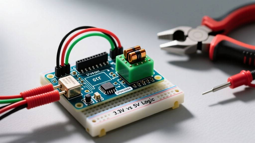
If you are upgrading from a 5V Arduino to a 3.3V board like the ESP32-S3 or Raspberry Pi Pico (RP2040), you will encounter a logic level mismatch. A standard 5V relay module requires a logic HIGH of at least 3.5V to reliably turn off the optocoupler LED. A 3.3V GPIO pin cannot provide this, resulting in a relay that chatters, stays permanently stuck ON, or overheats the ESP32.
Expert Tip: The JD-VCC Jumper
Most high-quality 5V relay modules feature a jumper labeledJD-VCC. By removing this jumper, you separate the relay coil power from the optocoupler LED power. You can feed 5V into the JD-VCC pins to drive the heavy coil, while feeding 3.3V into the standard VCC pin to power the optocoupler LED. This allows perfect, safe operation with 3.3V microcontrollers without needing external logic level shifters.
For permanent installations, consider skipping the blue hobbyist modules entirely. According to the Official Arduino Hardware Documentation and industrial safety standards, cheap modules often lack the required creepage and clearance distances mandated by IEC 61010-1 for mains voltage. For 120V/240V AC, use DIN-rail mounted relays like the Finder 38.51 or solid-state relays (SSRs) like the Omron G3MB-202P, which hover around $3.50 to $5.00 in 2026 and offer zero-contact-bounce switching.
Non-Blocking Relay Control Code
Using the delay() function in Arduino sketches is a notorious anti-pattern that halts the microcontroller, preventing it from reading sensors or processing network data. Below is a production-ready, non-blocking implementation using millis() to toggle a relevador every 5 seconds without freezing the CPU.
const int RELAY_PIN = 8;
const unsigned long INTERVAL_MS = 5000;

unsigned long previousMillis = 0;
bool relayState = false;

void setup() {
  pinMode(RELAY_PIN, OUTPUT);
  // Initialize relay in the OFF state (assuming Low-Level Trigger module)
  digitalWrite(RELAY_PIN, HIGH);
  Serial.begin(115200);
}

void loop() {
  unsigned long currentMillis = millis();

  if (currentMillis - previousMillis >= INTERVAL_MS) {
    previousMillis = currentMillis;
    relayState = !relayState; // Toggle boolean state

    // Write inverted state for Low-Level Trigger modules
    digitalWrite(RELAY_PIN, relayState ? LOW : HIGH);

    Serial.print("Relay is now: ");
    Serial.println(relayState ? "ON" : "OFF");
  }

  // CPU is free to handle WiFi, sensors, or button debouncing here
}
Common Failure Modes and Edge Cases
Even with correct wiring, relays in microcontroller circuits fail in predictable ways. Recognizing these edge cases separates hobbyists from professional embedded engineers.
1. Contact Welding on Inductive Loads
If you use a standard 10A electromechanical relay to switch a large DC motor or a transformer, the inrush current can be 5x to 10x the rated running current. When the contacts open, the resulting DC arc can melt the silver-alloy contact pads, welding them together. The relay will fail in the "ON" position, creating a severe safety hazard. Solution: Use a Solid State Relay (SSR) for high-inrush DC loads, or heavily oversize your electromechanical relay (e.g., use a 30A contactor for a 5A motor).
2. Optocoupler LED Degradation
The PC817 optocouplers used on budget modules have a finite lifespan. If your firmware accidentally leaves the GPIO pin LOW (activating the optocoupler LED) for days at a time, the internal LED will dim and eventually fail, causing the relay to stop triggering. Solution: Design your circuit so the relay is only energized for the brief moments it needs to actuate, or use latching relays (like the Omron G5V-2) which only require a pulse to change state.
3. Mains Noise and Brownouts
Switching heavy AC loads generates massive electromagnetic interference (EMI) that can couple back into your Arduino's power supply, causing brownouts and random reboots. Solution: Route AC mains wiring at least 2 inches away from low-voltage DC signal wires. Place a 0.1µF ceramic decoupling capacitor directly across the 5V and GND pins on the Arduino breadboard, and consider using a dedicated isolated buck converter for the relay module's power supply.
Summary
Mastering the relevador arduino interface requires more than just copying a wiring diagram. It demands an understanding of coil current requirements, back-EMF protection, logic level compatibility, and the physical limitations of electromechanical contacts. By calculating your load requirements, utilizing non-blocking code, and respecting mains voltage safety clearances, you can build robust, industrial-grade automation systems using accessible microcontroller hardware. For deeper dives into component selection, always consult manufacturer datasheets and resources like Texas Instruments application notes on inductive load switching.