
The MAX30205 Clinical Sensor: When Precision Meets I2C Frustration
The Analog Devices (formerly Maxim Integrated) MAX30205 is a staple in 2026 for DIY clinical thermometers, incubator monitors, and high-end wearable health devices. Offering an impressive ±0.1°C accuracy over the critical 37°C to 39°C human body temperature range, it vastly outperforms standard NTC thermistors. However, integrating the MAX30205 with Arduino ecosystems frequently triggers I2C bus errors, silent NACK failures, and erratic thermal readings. This guide provides a deep-dive diagnostic framework to isolate hardware faults, logic-level mismatches, and register timing violations when your MAX30205 Arduino setup refuses to cooperate.
Decoding Wire.endTransmission() Error Codes
When your Arduino sketch fails to pull data from the sensor, the first diagnostic step is checking the return value of the Wire.endTransmission() function. Many makers ignore this integer, but it pinpoints the exact failure node on the I2C bus.
| Return Code | Meaning | MAX30205 Specific Root Cause |
|---|---|---|
| 0 | Success | Data transmitted successfully. |
| 1 | Data too long | Buffer overflow in the Wire library (rare for this sensor). |
| 2 | NACK on Address | Logic voltage mismatch, missing pull-ups, or incorrect A0/A1/A2 strapping. |
| 3 | NACK on Data | Attempting to write to a read-only register or timing violation. |
| 4 | Other Error | I2C bus lockup, SDA line held low by sensor or parasitic capacitance. |
Hardware Diagnosis: The 5V vs 3.3V Logic Trap
The most common cause of Error 2 (NACK on Address) when using a MAX30205 Arduino setup is a logic voltage mismatch. The MAX30205MTA+ operates strictly on 2.7V to 3.3V logic. Connecting its SDA and SCL lines directly to a 5V Arduino Uno or Mega will not only result in I2C bus lockups but can permanently degrade the sensor's internal ESD protection diodes, leading to intermittent failures that are notoriously difficult to debug.
Expert Warning: Do not rely on internal microcontroller clamping diodes to drop 5V to 3.3V. This will inject noise into the MAX30205 analog front-end, destroying the ±0.1°C accuracy. Always use a dedicated level shifter.The BSS138 Level Shifter Solution
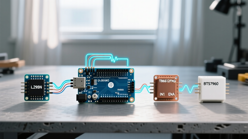
If you are using a 5V Arduino, you must route the I2C lines through a bidirectional logic level converter based on the BSS138 MOSFET ($1.50 to $3.00 for breakout modules). Ensure the high-voltage side (HV) is connected to the Arduino 5V, and the low-voltage side (LV) is connected to a clean 3.3V rail. Furthermore, verify that your breakout board includes 4.7kΩ pull-up resistors on the 3.3V side. If the I2C bus capacitance exceeds 200pF due to long wires, drop the pull-ups to 2.2kΩ to sharpen the signal rise times, as detailed in the NXP I2C-bus Specification.
I2C Address Strapping and Conflict Resolution
The MAX30205 features three address pins (A0, A1, A2), allowing up to eight sensors on the same bus. The base I2C address is 0x48. If your i2c_scanner sketch shows no devices, or shows a device at an unexpected address, verify the physical strapping on your breakout board.
- 0x48: A0=GND, A1=GND, A2=GND (Default on most AliExpress/Amazon breakouts)
- 0x49: A0=VDD, A1=GND, A2=GND
- 0x4A: A0=GND, A1=VDD, A2=GND
- 0x4B: A0=VDD, A1=VDD, A2=GND
Use a multimeter in continuity mode to verify that the A0/A1/A2 pads are actually bridged to GND or VDD as the silkscreen suggests. Manufacturing defects on cheap breakout boards occasionally leave these pins floating, causing the sensor to dynamically shift addresses based on ambient EMI.
Software Timing: The Data Ready Bit Bottleneck
A frequent software-level error is reading the Temperature Register (0x00) before the analog-to-digital conversion is complete. If you read the register prematurely, the MAX30205 will return stale data or 0xFFFF, which translates to an erroneous spike in your serial monitor.
Proper Register Polling Sequence
- Write to the Configuration Register (0x01) to set the Shutdown bit (D0) to 0, ensuring continuous conversion, OR trigger a One-Shot conversion by setting D1 to 1.
- Wait for the conversion time. The MAX30205 requires a maximum of 50ms for a 16-bit conversion.
- Read two bytes from the Temperature Register (0x00).
- Apply the bitwise conversion: The data is 16-bit two's complement, but the lower 3 bits are unused. You must right-shift the raw integer by 3, then multiply by the resolution factor of
0.00390625.
Code Snippet Logic:
int16_t raw = (Wire.read() << 8) | Wire.read();
raw = raw >> 3;
float tempC = raw * 0.00390625;
For deeper register mapping and timing diagrams, always refer to the official Analog Devices MAX30205 Product Page and datasheet.
Thermal Gradient and Self-Heating Errors
If your hardware and software are flawless, but your readings show a steady +0.4°C offset or gradual upward drift, you are experiencing thermal gradient errors. The MAX30205 is exceptionally sensitive to PCB self-heating.
Diagnosing PCB Heat Soak
Many commercial MAX30205 breakout boards integrate an onboard AMS1117-3.3V linear voltage regulator. If you power the module with 5V, the LDO dissipates excess voltage as heat. Even a 10mA current draw can raise the local PCB temperature by 1°C to 2°C, completely ruining the clinical accuracy of the sensor. To diagnose this, power the breakout board directly with a clean 3.3V source, bypassing the onboard LDO entirely. If the temperature reading drops and stabilizes, the LDO was your culprit.
For wearable or skin-contact applications, use a flexible printed circuit (FPC) tail to physically separate the MAX30205 sensor die from the main microcontroller PCB. This prevents the MCU's processing heat from conducting through the copper ground planes into the sensor's thermal mass.
Step-by-Step Diagnostic Flowchart
When facing a non-responsive MAX30205 Arduino integration, follow this strict isolation sequence:
- Verify Power: Measure VDD at the sensor pins with a multimeter. It must be between 2.7V and 3.3V. Anything above 3.6V risks permanent silicon damage.
- Check Pull-ups: Measure resistance between SDA/SCL and VDD. You should see ~4.7kΩ. If infinite, add external pull-ups.
- Run I2C Scanner: Upload the standard Arduino Wire Scanner sketch. If it hangs, your SDA line is being held low (Error 4). Reset the bus by toggling the SCL pin manually 9 times via GPIO bit-banging.
- Validate Logic Levels: Hook an oscilloscope or logic analyzer to SDA. Verify the high-state voltage matches the sensor's VDD, not the Arduino's 5V.
- Confirm Timing: Insert a
delay(60);after triggering a one-shot read to rule out ADC conversion lag.
Summary and Best Practices
Mastering the MAX30205 on Arduino requires respecting its strict low-voltage requirements and precise I2C timing. By utilizing BSS138 level shifters, bypassing noisy onboard LDOs, and implementing proper bitwise data extraction, you can reliably achieve the clinical-grade ±0.1°C accuracy this sensor was designed for. Always consult the Arduino Wire Library Reference when debugging complex I2C state machines to ensure your buffer management aligns with the sensor's register expectations.