
Why the Automotive Environment Destroys Standard Microcontrollers
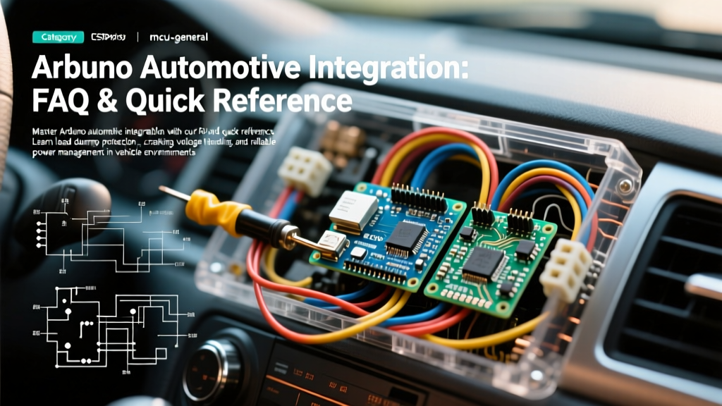
Integrating an Arduino automotive project into a vehicle is not as simple as tapping into the 12V cigarette lighter. The modern vehicle electrical system is a notoriously hostile environment characterized by extreme voltage transients, electromagnetic interference (EMI), and severe temperature fluctuations. A standard Arduino Uno powered directly from a car battery will likely suffer catastrophic failure within minutes due to load dumps or alternator ripple.
This FAQ and quick reference guide provides actionable, expert-level engineering solutions for hardening your microcontroller designs against the rigorous demands of automotive applications in 2026.
Power Supply Survival: Load Dumps and Cranking Drops
Q: Can I use a standard LM7805 or cheap LM2596 buck converter for automotive power?
No. Standard linear regulators and basic switching converters are rated for maximum input voltages of 35V to 40V. During a "load dump" event (ISO 7637-2 Pulse 5), which occurs when a discharged battery is disconnected while the alternator is charging, voltage spikes can reach 40V to 120V for hundreds of milliseconds. This will instantly vaporize the input capacitor and silicon of a standard regulator.
The Expert Solution: Implement a multi-stage power conditioning circuit:
- Stage 1 (Transient Clamping): Place a bidirectional TVS (Transient Voltage Suppressor) diode, such as the SMAJ24CA or SMCJ24CA, directly across the 12V input. This clamps load dump spikes to a safe ~27V.
- Stage 2 (Reverse Polarity & Ripple): Use a Schottky diode (e.g., 1N5822) to prevent reverse battery connection and block negative transients.
- Stage 3 (Step-Down Conversion): Use an automotive-grade, wide-input buck converter like the LM2576HV (rated up to 60V) or a modern synchronous buck like the TI LM53615 to step the clamped voltage down to a clean 5V or 3.3V.
Q: Why does my Arduino reboot when I start the engine?
This is caused by ISO 7637-2 Pulse 4 (Cranking Voltage Drop). When the starter motor engages, system voltage can drop to 6V or lower for several seconds. The onboard linear regulator of a standard Arduino requires at least 7V input to maintain a stable 5V output (due to dropout voltage), causing the ATmega328P to brown out and reset.
The Expert Solution: Use a SEPIC or Buck-Boost converter topology. Chips like the LTC3110 or TI TPS63020 maintain a steady 5V output even when the input voltage sags to 4V during engine cranking. Expect to pay around $12 to $18 for a pre-built SEPIC module in 2026.
Quick Reference: ISO 7637-2 Automotive Transients
According to Texas Instruments Automotive Solutions guidelines, designing for ISO 7637-2 compliance is mandatory for reliable ECU operation. Below is a quick reference matrix for mitigating standard pulses:
| Pulse | Description | Peak Voltage | Hardware Mitigation Strategy |
|---|---|---|---|
| Pulse 1 | Inductive load interruption (negative spike) | -25V to -100V | TVS Diode + Series Schottky Diode |
| Pulse 2a | Wiring harness inductance (positive spike) | +37V to +112V | TVS Diode + Input Capacitance |
| Pulse 3a/3b | High-speed switching transients | -150V / +75V | Ferrite beads + Ceramic Bypass Caps (100nF) |
| Pulse 4 | Starter motor cranking drop | Drops to 4V - 6V | Buck-Boost / SEPIC Regulator |
| Pulse 5a/5b | Alternator Load Dump | +40V to +120V | High-Power TVS (SMCJ series) + Crowbar Circuit |
Input/Output Protection: Interfacing with 12V Systems
Q: How do I safely read 12V automotive sensors (e.g., MAP, Tachometer)?
Never use a simple resistive voltage divider to read automotive signals. Voltage dividers offer zero isolation and will pass high-voltage spikes directly into the Arduino's GPIO pins, destroying the microcontroller.
The Expert Solution:
- Optocouplers: Use a PC817 or 4N35 optocoupler. Place a 2.2kΩ resistor on the 12V input side to limit current to ~5mA. This provides complete galvanic isolation.
- Logic-Level MOSFETs: For high-frequency signals (like fuel injector pulses), an optocoupler may be too slow. Use an N-channel logic-level MOSFET (e.g., 2N7000) with a 10kΩ pull-up resistor on the Arduino side and a 5.1V Zener diode clamping the gate to protect against overvoltage.
Q: What is required to drive automotive relays?
When driving high-current loads like fuel pumps, radiator fans, or lighting via automotive relays, the relay coil acts as a massive inductor. When the Arduino turns off the MOSFET or BJT driving the coil, the collapsing magnetic field generates a high-voltage flyback spike.
Critical Rule: Never drive a relay coil without a flyback diode. As detailed in the SparkFun Relays Tutorial, placing a 1N4007 or 1N5819 diode in reverse-bias across the relay coil terminals is mandatory to prevent the flyback spike from frying your driving transistor and feeding noise back into the 5V rail.
Environmental Hardening: Temperature, Vibration, and EMI
Q: Can I mount an Arduino under the hood?
Generally, no. While the ATmega328P silicon is rated for industrial temperatures (-40°C to +85°C), the electrolytic capacitors and linear regulators on commercial Arduino boards will degrade rapidly or fail at under-hood temperatures, which frequently exceed 100°C in summer traffic.
Best Practices for Harsh Environments:
- Location: Mount the ECU in the cabin (under the dash or behind the glovebox) where temperatures remain stable. Route sensor wiring through the firewall using sealed grommets.
- Conformal Coating: If cabin mounting isn't possible, coat the PCB with an automotive-grade silicone conformal coating like MG Chemicals 422C. This protects against humidity, condensation, and corrosive road salts.
- Vibration Proofing: Avoid solderless breadboards entirely. Use screw-terminal shields or, preferably, design a custom PCB. Pot the entire enclosure in a soft polyurethane potting compound (e.g., Electrolube UR5634) to dampen high-frequency engine vibrations.
Q: How do I prevent CAN bus and sensor noise (EMI)?
Ignition coils and alternators generate massive electromagnetic interference. If you are using an MCP2515 CAN bus module to read OBD2 data, or reading analog sensors, noise will corrupt your readings.
- Twisted Pairs: Always use twisted pair wiring for CAN High and CAN Low. Maintain a strict 120-ohm impedance and terminate both ends of the bus with 120Ω resistors.
- Shielding: Use shielded cables for analog sensors (like wideband O2 sensors). Ground the shield only at the ECU end to prevent ground loops.
- Star Grounding: Implement a strict star-ground topology. All sensor grounds, power grounds, and communication grounds should meet at a single, heavy-gauge grounding point bolted directly to the chassis. Never daisy-chain grounds.
Recommended Hardware for Automotive Projects
If you are moving past prototyping and building a permanent automotive installation, consider upgrading from a standard $27 Arduino Uno to specialized hardware:
- Ruggeduino Uno: Priced around $75, the Rugged Circuits Ruggeduino features built-in overvoltage protection on all I/O pins, a protected USB port, and a robust power supply designed specifically for harsh industrial and automotive environments.
- Teensy 4.1: For high-speed data logging (e.g., capturing 500Hz suspension telemetry or high-res engine mapping), the Teensy 4.1 (approx. $38) offers a 600MHz ARM Cortex-M7, native SDIO for SD cards, and multiple CAN bus interfaces, though it requires careful custom power regulation due to its 3.3V logic and low voltage tolerance.
- Controllino / Industrial Shields: For heavy-duty commercial vehicle applications (trucks, marine), PLC-style Arduino-compatible boards ($150 - $300) provide opto-isolated inputs, high-side MOSFET outputs, and DIN-rail mounting out of the box.
By respecting automotive electrical standards and implementing robust front-end protection, your Arduino-based ECU, datalogger, or custom lighting controller will survive the harsh realities of the road for years to come.