
Understanding Arduino Digital Input Thresholds
When working with microcontrollers, reading a digital input seems trivial: a pin is either HIGH (1) or LOW (0). However, treating an Arduino digital input as a simple binary switch without understanding the underlying hardware physics is the leading cause of erratic behavior in beginner and intermediate maker projects. Whether you are using a classic 5V AVR-based board or a modern 3.3V ARM/ESP32 architecture, mastering digital inputs requires a firm grasp of voltage thresholds, pull configurations, and mechanical switch realities.
Microcontrollers do not read '1' or '0' directly; they read analog voltages and compare them against internal reference thresholds. For the ubiquitous ATmega328P (found in the Arduino Uno), the logic high threshold ($V_{IH}$) is typically 0.6 × VCC (3.0V on a 5V board), and the logic low threshold ($V_{IL}$) is 0.3 × VCC (1.5V). Any voltage floating between 1.5V and 3.0V is in an undefined state, which can cause the microcontroller to read random noise, overheat the input buffer, or trigger phantom interrupts. For a comprehensive breakdown of the syntax used to read these states, refer to Arduino's official digitalRead() documentation.
The Danger of the Floating Pin
If you wire a tactile switch directly to a digital pin and ground, but leave the pin disconnected when the switch is open, the pin becomes 'floating.' A floating pin acts as a high-impedance antenna, picking up electromagnetic interference (EMI) from nearby wires, switching power supplies, and even your body's capacitance. To prevent this, we must use a pull resistor to force the pin into a known state when the switch is open.
Wiring Configurations: Pull-Up vs. Pull-Down
You have three primary methods to bias an Arduino digital input. The choice dictates both your wiring topology and your firmware logic.
| Configuration | Wiring Topology | Open Switch State | Closed Switch State | Hardware Required |
|---|---|---|---|---|
| External Pull-Down | Pin to Switch to VCC; 10kΩ resistor from Pin to GND | LOW (0V) | HIGH (5V/3.3V) | 10kΩ Resistor |
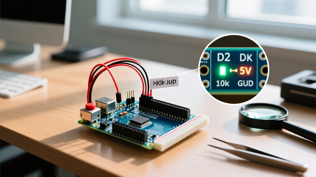
| External Pull-Up | Pin to Switch to GND; 10kΩ resistor from Pin to VCC | HIGH (5V/3.3V) | LOW (0V) | 10kΩ Resistor |
| Internal Pull-Up | Pin to Switch to GND | HIGH (5V/3.3V) | LOW (0V) | None (Enabled in code) |
Pro-Tip for 2026 Builds: While the internal pull-up resistor (typically 20kΩ to 50kΩ on AVR chips) is convenient, it is relatively weak. If your project operates in an electrically noisy environment—such as near stepper motors or AC relays—use an external 4.7kΩ or 10kΩ pull-up resistor to create a stronger, more noise-immune bias. Read more about the physics of biasing in this excellent SparkFun guide on pull-up resistors.
Step-by-Step Wiring Guide (Active-Low Configuration)
The industry standard for digital inputs is the 'Active-Low' configuration using a pull-up resistor. This means the microcontroller reads HIGH when idle, and LOW when the button is pressed. We will use an Arduino Uno R4 Minima (retailing around $27.50 in 2026) and a standard 6x6mm tactile switch.
- Power the Breadboard: Connect the Uno's 5V pin to the breadboard's positive rail and GND to the negative rail.
- Place the Switch: Insert the tactile switch across the breadboard's center trench so each pair of legs is on a separate side.
- Wire the Signal: Connect one leg of the switch to Digital Pin 2 on the Arduino.
- Wire Ground: Connect the opposite leg of the switch to the breadboard's GND rail.
- Add the Resistor: Insert a 10kΩ resistor connecting the Digital Pin 2 row to the 5V positive rail. (Note: If using the internal pull-up, skip this step).
Writing the Firmware: Basic digitalRead()
With the hardware biased correctly, we can write the firmware. If you are using an external pull-down resistor, configure the pin as INPUT. If you are using a switch wired to ground with no external resistor, configure it as INPUT_PULLUP to engage the microcontroller's internal bias.
const int buttonPin = 2;
int buttonState = 0;

void setup() {
  Serial.begin(115200);
  // Using internal pull-up for a switch wired between Pin 2 and GND
  pinMode(buttonPin, INPUT_PULLUP);
}

void loop() {
  // Read the state of the pushbutton
  buttonState = digitalRead(buttonPin);

  // Because of the pull-up, LOW means the button is pressed
  if (buttonState == LOW) {
    Serial.println('Button Pressed');
  } else {
    Serial.println('Button Released');
  }
  delay(50); // Naive delay, see debouncing section below
}
The Hidden Enemy: Switch Bounce and Debouncing
Mechanical switches do not make a clean electrical connection. When the metal contacts close, they physically bounce against each other for 1 to 5 milliseconds before settling. To a microcontroller executing millions of instructions per second, this bounce looks like the button was pressed and released dozens of times in rapid succession. If your code increments a counter or toggles an LED on a button press, switch bounce will cause wildly inaccurate results.
While beginners often use delay(50) to 'debounce' a switch, this halts the entire microcontroller, preventing it from reading sensors or updating displays. The professional approach is a non-blocking state machine using the millis() function. For a deeper dive into the oscilloscope traces of contact bounce, review this technical article on switch bounce and mitigation strategies from All About Circuits.
Non-Blocking Debounce Code Implementation
The following code tracks the last time the pin changed state and ignores any subsequent changes that occur within a 50-millisecond window.
const int buttonPin = 2;
int lastStableState = HIGH;   // The last stable state sent to the logic
int currentReading;           // The raw reading from the pin
unsigned long lastDebounceTime = 0;
unsigned long debounceDelay = 50; // 50ms debounce window

void setup() {
  Serial.begin(115200);
  pinMode(buttonPin, INPUT_PULLUP);
}

void loop() {
  int reading = digitalRead(buttonPin);

  // Check if the raw reading differs from the last stable reading
  if (reading != lastStableState) {
    // Reset the debouncing timer
    lastDebounceTime = millis();
  }

  // If the state has been stable for longer than the debounce delay
  if ((millis() - lastDebounceTime) > debounceDelay) {
    // If the raw reading is different from the current reading, update it
    if (reading != currentReading) {
      currentReading = reading;

      // Active-low logic: LOW means pressed
      if (currentReading == LOW) {
        Serial.println('Debounced Press Detected');
      }
    }
  }

  lastStableState = reading;
}
Troubleshooting Edge Cases and Hardware Failures
Even with perfect code, physical hardware can introduce faults. Here is how to diagnose common Arduino digital input failures using a standard digital multimeter (DMM).
- Logic Level Mismatch (The 3.3V Trap): If you are upgrading from an Uno (5V logic) to an Arduino Nano ESP32 or Portenta H7 (3.3V logic), feeding a 5V signal into a 3.3V digital input will permanently damage the GPIO pin. Always use a logic level converter or a simple voltage divider (e.g., 2kΩ and 3.3kΩ resistors) when interfacing 5V sensors with 3.3V MCUs.
- Corroded Switch Contacts: If your DMM shows a voltage drop of more than 0.2V across a closed tactile switch, the internal contacts are oxidized. Replace the switch or use a hardware Schmitt trigger (like the 74HC14) to clean up the degraded signal edges.
- Ground Loop Noise: If your digital input triggers randomly when a nearby relay switches, your ground return path is shared. Route the digital input's ground wire directly to the microcontroller's star-ground point, completely separate from high-current motor or relay grounds.
Summary Checklist for Reliable Inputs
Before finalizing your PCB design or permanent breadboard build, verify these four parameters:
- Is the pin biased (pull-up or pull-down) to prevent floating?
- Does the signal voltage respect the microcontroller's VCC logic thresholds?
- Is the firmware utilizing a non-blocking debounce algorithm?
- Are high-current ground returns isolated from the logic ground path?
By respecting the electrical realities of the Arduino digital input circuit, you transition from writing code that 'mostly works' to engineering robust, industrial-grade embedded systems that perform flawlessly in the real world.