
The Core Architecture of Smartphone-to-MCU Control
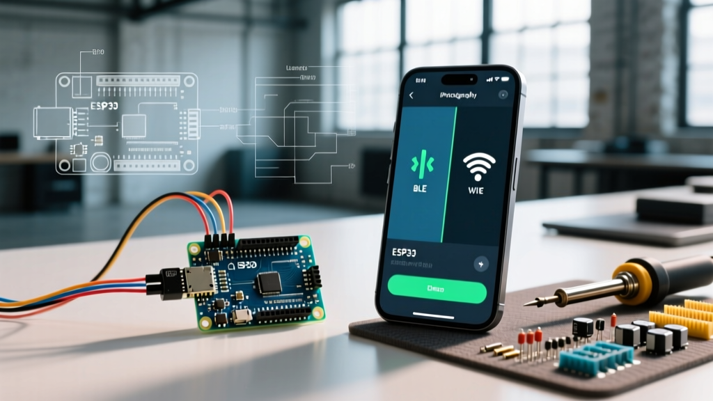
When exploring how to control Arduino remotely using a smartphone, makers and engineers generally choose between two distinct wireless paradigms: short-range Bluetooth Low Energy (BLE) and long-range WiFi utilizing cloud brokers. Understanding the architectural differences between these two methods is critical before writing a single line of firmware. A smartphone does not natively 'talk' to a microcontroller's GPIO pins; instead, it acts as a client or publisher that sends serialized data payloads over a specific RF protocol, which the MCU must then decode into physical voltage states.
In 2026, the landscape of mobile-to-MCU control has matured. We no longer rely on clunky, raw TCP socket connections or deprecated Bluetooth Classic serial modules like the HC-05. Modern implementations leverage BLE 5.0 GATT profiles and MQTT v5.0 Pub/Sub architectures. This guide breaks down the exact hardware, protocols, and edge cases for both approaches.
Method 1: Short-Range Control via Bluetooth Low Energy (BLE)
The BLE approach is ideal for localized, low-power applications such as custom RC vehicles, smart locks, or wearable prototypes. In this model, the smartphone and the Arduino communicate directly (peer-to-peer) without requiring an internet connection or a local router.
Understanding the GATT Protocol
Unlike the old serial-over-Bluetooth method, BLE uses the Generic Attribute Profile (GATT). According to the official Arduino BLE documentation, GATT organizes data into a hierarchy of Services and Characteristics.
- Service: A 128-bit UUID that acts as a folder (e.g., a 'Smart Home' service).
- Characteristic: A specific data point within that service (e.g., 'Living Room Relay State') that can be read, written, or subscribed to for notifications.
When your smartphone app connects to an Arduino Nano 33 BLE (which features the Nordic nRF52840 chip, currently priced around $24), the phone acts as the GATT Client and the Arduino acts as the GATT Server. The phone writes a hex value (e.g., 0x01) to the Characteristic, and the Arduino's firmware intercepts this write event to trigger a digital pin.
Hardware & App Selection
For BLE, the Arduino Nano 33 BLE Sense Rev2 is the industry standard for makers. To build the smartphone interface without writing native Swift or Kotlin code, developers use MIT App Inventor (utilizing its BLE extension) or generic testing apps like nRF Connect for rapid prototyping.
Method 2: Global Control via WiFi and MQTT
If your project requires control from outside your home network—or if you need to integrate the Arduino into a broader ecosystem like Home Assistant—WiFi paired with the MQTT protocol is the mandatory choice.
The Pub/Sub Paradigm
WiFi MCUs do not typically host web servers that smartphones connect to directly, as this exposes the device to security risks and NAT traversal issues. Instead, we use MQTT (Message Queuing Telemetry Transport). As defined by the OASIS MQTT v5.0 standard, MQTT relies on a central Broker.
Concept Note: The smartphone and the Arduino never connect to each other. They both connect to a cloud Broker (like AWS IoT, Mosquitto, or Blynk). The Arduino subscribes to a topic like
home/office/relay/cmd, and the smartphone publishes an 'ON' payload to that exact same topic.
Hardware & Cloud Brokers
The ESP32-WROOM-32E DevKit V1 (approx. $6 to $9) is the undisputed king of WiFi MCU control. It features dual-core processing and dedicated hardware acceleration for TLS/SSL encryption. For the smartphone app, platforms like Blynk IoT (which offers a free tier allowing up to 2 devices and 5 templates in 2026) provide drag-and-drop UI widgets that automatically map to MQTT topics or proprietary TCP streams.
Head-to-Head Comparison: BLE vs. WiFi
Choosing the right protocol dictates your entire hardware stack. Review the matrix below to align the technology with your project requirements.
| Feature | BLE 5.0 (Arduino Nano 33 BLE) | WiFi / MQTT (ESP32-WROOM-32E) |
|---|---|---|
| Operational Range | 10 - 30 meters (Line of Sight) | Global (Requires Internet & Router) |
| Power Consumption | Ultra-Low (~10µA in sleep) | High (~160mA during TX bursts) |
| Latency | 3ms - 15ms (Direct Peer-to-Peer) | 50ms - 300ms (Cloud Broker Routing) |
| Network Setup | None (Auto-discovery via MAC) | Requires SSID/Password Hardcoding |
| Ideal Use Case | RC Cars, Wearables, Proximity Locks | Smart Plugs, Irrigation, Telemetry |
Critical Edge Cases and Troubleshooting
When learning how to control Arduino remotely using a smartphone, tutorials often gloss over the failure modes that occur in real-world environments. Here are the most common edge cases and their engineering solutions.
1. The ESP32 2.4GHz WiFi Blindspot
A frequent point of failure is the ESP32 refusing to connect to a modern home router. The ESP32's WiFi radio only supports 802.11 b/g/n on the 2.4GHz band. It physically cannot see 5GHz networks, nor can it connect to WiFi 6 (802.11ax) if the router is configured to 'AX-only' mode. Furthermore, as noted in the Espressif WiFi API Guide, the ESP32 struggles with WPA3-SAE authentication on certain older firmware cores. Fix: Create a dedicated 2.4GHz WPA2 guest network on your router specifically for IoT devices.
2. BLE MTU Payload Truncation
By default, the BLE Maximum Transmission Unit (MTU) is limited to 23 bytes, leaving only 20 bytes for actual payload data. If your smartphone app attempts to send a complex JSON string (e.g., {"color":"#FF00FF","brightness":255}) that exceeds 20 bytes, the Arduino will only receive the first chunk, resulting in a JSON parsing crash. Fix: Implement MTU negotiation in your smartphone app code to request a higher MTU (up to 247 bytes in BLE 4.2+), and implement a reassembly buffer on the Arduino side.
3. State Desynchronization
Imagine controlling a relay via WiFi. You press 'ON' on your phone, but the phone momentarily loses cell service before receiving the broker's acknowledgment. The UI reverts to 'OFF', but the physical relay remains 'ON'. Fix: Never rely on the smartphone's UI state. The app must subscribe to the MCU's status topic (e.g., home/relay/state). The MCU publishes its actual GPIO state back to the broker, and the phone updates its UI only when it receives this verified telemetry.
Designing a Non-Blocking State Machine
Whether using BLE or WiFi, the most critical rule in MCU firmware design is never use the delay() function. Wireless stacks require constant background processing to maintain connections, respond to ping requests, and negotiate encryption keys. A blocking delay of even 500 milliseconds can cause a BLE disconnect or an MQTT broker timeout.
Instead, structure your loop() using a millis()-based state machine. Check for incoming wireless events, update local state variables, and use hardware timers or non-blocking timestamps to handle physical outputs like PWM fading or relay debouncing. This ensures your smartphone commands are processed with sub-millisecond latency, regardless of what other tasks the microcontroller is executing.