
Introduction to AND Logic in Microcontrollers
Whether you are an English-speaking maker or a bilingual hobbyist searching for "AND en Arduino", understanding AND logic is a fundamental milestone in embedded systems engineering. In the Arduino ecosystem, AND logic can be implemented in two distinct ways: via software using C++ logical operators, or via hardware using external CMOS logic gates. While software logic is free and flexible, hardware logic provides deterministic timing, failsafe interlocks, and offloads the microcontroller unit (MCU).
This configuration guide breaks down the exact syntax, compiler behaviors, and physical wiring requirements for implementing AND logic on modern boards like the Arduino Uno R4 Minima and the Nano ESP32. We will move beyond basic tutorials to explore edge cases like short-circuit evaluation bugs and CMOS floating-pin oscillation.
Software Configuration: Logical vs. Bitwise AND
When writing sketches in the Arduino IDE, developers frequently confuse the logical AND (&&) with the bitwise AND (&). Understanding how the GCC AVR compiler (and ARM Clang for R4 boards) handles these operators is critical for writing bug-free firmware.
The Logical AND (&&) and Short-Circuit Evaluation
The logical AND operator evaluates to true (1) only if both operands are non-zero. Crucially, C++ employs short-circuit evaluation. If the left operand evaluates to false, the right operand is never executed. This saves CPU cycles but can introduce severe bugs if the right operand contains a side effect, such as reading from an I2C sensor or clearing a volatile hardware register.
// DANGEROUS: If sensorA is false, readI2CSensor() is NEVER called.
if (sensorA && readI2CSensor()) {
  triggerAlarm();
}
For a comprehensive breakdown of operator precedence and evaluation rules, consult the Arduino Official Reference for Logical AND.
The Bitwise AND (&)
The bitwise AND operates on the individual binary bits of a byte or integer. It does not short-circuit. Both sides are always evaluated. This is heavily used in register manipulation, such as masking specific bits in a port register or checking the status of a hardware interrupt flag.
| Feature | Logical AND (&&) |
Bitwise AND (&) |
|---|---|---|
| Operand Type | Booleans, Integers (evaluated as true/false) | Integers, Bytes, Hexadecimal masks |
| Short-Circuiting | Yes (Right side skipped if left is false) | No (Both sides always evaluated) |
| Primary Use Case | Control flow, conditional state machines | Register masking, bit extraction, cryptography |
| Execution Speed | Variable (depends on short-circuit) | Constant (typically 1-2 clock cycles) |
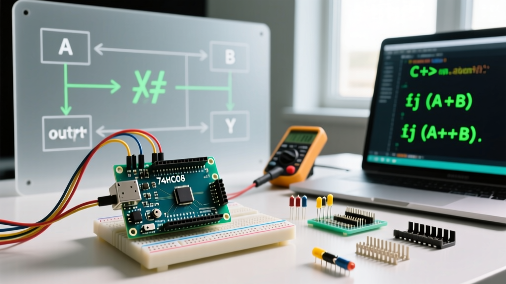
Hardware Configuration: Wiring the 74HC08 AND Gate
Software logic requires the MCU to be powered, booted, and actively running its main loop. In industrial and automotive applications, this is unacceptable for safety interlocks. If a CNC router's physical emergency stop and limit switch must both be engaged to kill the spindle relay, a hardware AND gate ensures the interlock functions even if the Arduino crashes or is unpowered.
The industry standard for this is the Texas Instruments SN74HC08N, a Quad 2-Input AND Gate. As of early 2026, this DIP-14 IC costs approximately $0.65 at major distributors like Mouser or DigiKey. For detailed pinout and electrical characteristics, refer to the TI SN74HC08 Product Page.
Crucial E-E-A-T Note: HC vs. HCT vs. LS Logic Families
Do not use the older 74LS08 (TTL logic). The LS family requires a strict 5V supply and has a high logic threshold that may not register a 3.3V HIGH signal from modern MCUs like the Nano ESP32. The 74HC series is CMOS-based, operating reliably from 2.0V to 6.0V, making it perfectly compatible with both 5V (Uno R4) and 3.3V (ESP32) logic levels.
Component List & 2026 Pricing
- MCU: Arduino Uno R4 Minima (~$27.50) or Nano ESP32 (~$29.00). See the Arduino Uno R4 Minima Documentation for pinout specifics.
- Logic IC: SN74HC08N Quad AND Gate (~$0.65).
- Resistors: 10kΩ pull-down resistors (x2) and 220Ω current-limiting resistor (x1).
- Indicators: 5mm Red LED for output verification.
Step-by-Step Wiring Guide
- Power the IC: Connect Arduino 5V (or 3.3V) to Pin 14 (VCC) of the 74HC08. Connect Arduino GND to Pin 7 (GND) of the IC.
- Configure Inputs: Connect your two input signals (e.g., limit switches) to Pin 1 (1A) and Pin 2 (1B).
- Install Pull-Downs: Connect a 10kΩ resistor from Pin 1 to GND, and another 10kΩ resistor from Pin 2 to GND. Never leave CMOS inputs floating.
- Route the Output: Pin 3 (1Y) is the AND output. Connect a 220Ω resistor in series with an LED to GND for visual testing, or route it directly to an Arduino digital input pin (e.g., D2) configured with
INPUT_PULLUPdisabled.
Pro-Tip on Floating Pins: A common failure mode among beginners is leaving unused AND gates inside the 74HC08 chip unconnected. A floating CMOS input acts as an antenna, picking up RF noise. This causes the internal transistors to oscillate rapidly, leading to excessive current draw, chip overheating, and erratic behavior on the active gates. Always tie unused inputs (like pins 4, 5, 9, 10, 12, 13) directly to GND.
Real-World Edge Cases & Troubleshooting
1. Switch Bounce in Hardware Logic
Mechanical switches exhibit contact bounce, lasting anywhere from 1ms to 10ms. In software, we use debouncing algorithms. In hardware, the 74HC08 will faithfully output the bounce. If this output triggers a sensitive interrupt or a high-speed counter on the Arduino, you will register multiple false triggers. Solution: Place a 100nF ceramic capacitor in parallel with the 10kΩ pull-down resistor to create a hardware low-pass RC filter, effectively debouncing the signal before it reaches the logic gate.
2. The I2C Side-Effect Bug in Software
Returning to the software && operator: imagine a scenario where you are checking a local boolean flag and an external I2C temperature sensor. If you write if (systemArmed && checkTempSensor()), and systemArmed is false, the I2C bus is never polled. If your system relies on that polling to keep a watchdog timer or a background state-machine synchronized, your system will silently desynchronize. Always separate I2C reads from logical evaluations.
Software vs. Hardware: Decision Framework
When designing your architecture in 2026, use this framework to decide between software and hardware AND implementations:
| Scenario | Recommended Approach | Rationale |
|---|---|---|
| Safety Interlocks (E-Stops) | Hardware (74HC08) | Must function if MCU crashes, loses power, or enters a boot-loop. |
| Complex UI Menus | Software (&&) |
Requires state memory and variable tracking that hardware gates cannot provide. |
| High-Speed Signal Gating | Hardware (74HC08) | MCU GPIO toggling and loop latency introduce jitter; CMOS gates operate in nanoseconds. |
| Sensor Data Fusion | Software (& / &&) |
Requires mathematical weighting and floating-point calculations. |
Summary
Mastering the logical AND in Arduino requires looking past basic syntax. By understanding the compiler's short-circuit behavior, you prevent hidden state-machine bugs. By integrating external CMOS logic like the SN74HC08, you elevate your projects from fragile hobbyist prototypes to robust, industrial-grade systems capable of deterministic hardware failsafes. Whether you are writing C++ or wiring a breadboard, precision in your logic design is what separates a functioning prototype from a reliable product.