
Mastering the IR Remote Control Arduino Interface
Building a custom wireless interface using an IR remote control Arduino setup remains one of the most reliable methods for home automation, robotics, and custom media centers. Unlike Bluetooth or Wi-Fi, Infrared (IR) requires zero network configuration, offers sub-millisecond latency, and operates entirely offline. However, the internet is saturated with outdated tutorials using deprecated library syntax that will fail to compile on modern IDEs. In this comprehensive guide, we bypass basic LED-blinking examples and engineer a robust system capable of decoding NEC protocol signals and safely triggering high-voltage relays using the latest 2026 library standards.
Bill of Materials (2026 Market Pricing)
To build a production-ready prototype, you need components that balance cost with signal integrity. Generic clones work well for receivers, but relay modules require optocoupler isolation to protect your microcontroller from flyback voltage spikes.
| Component | Recommended Model / Spec | Est. Price (USD) |
|---|---|---|
| Microcontroller | Arduino Uno R3 (or Nano V3.0 ATmega328P) | $8.00 - $24.00 |
| IR Receiver | VS1838B 38kHz Breakout Board | $1.20 - $2.50 |
| IR Remote | Standard 24-Key NEC Protocol Remote | $2.00 - $4.00 |
| Switching Module | 5V Single-Channel Relay (Optocoupler Isolated) | $2.50 - $3.50 |
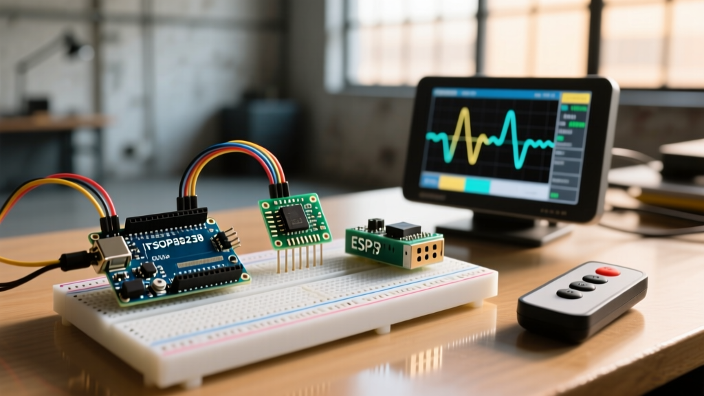
| Alternative Receiver | Vishay TSOP38238 (For high ambient light environments) | $3.50 - $5.00 |
The Physics of 38kHz IR Communication
Before wiring the circuit, it is critical to understand why IR remotes operate at a 38kHz carrier frequency. The sun and incandescent bulbs emit massive amounts of broadband infrared radiation. If an IR receiver simply looked for 'light', it would be blinded by ambient room lighting. By pulsing the IR LED at exactly 38,000 times per second (with a typical 33% duty cycle), the receiver's internal bandpass filter can ignore steady or slowly changing IR sources and only trigger when it detects this specific high-frequency pulse train. This technique, known as pulse distance encoding, is the backbone of the ubiquitous NEC protocol.
Expert Insight: If your project will be deployed outdoors or near a window with direct sunlight, the generic VS1838B receiver will likely suffer from 'saturation blindness'. Upgrade to the Vishay TSOP38238. According to Adafruit's IR Sensor Overview, Vishay's AGC (Automatic Gain Control) circuitry dynamically suppresses continuous 38kHz noise from compact fluorescent lamps (CFLs) and direct solar interference.
Wiring the Receiver: The Breakout Board Pinout Trap
A massive point of failure for beginners is the VS1838B breakout board pinout. The physical black sensor component has three legs: when facing the textured front, the pins are OUT (Left), GND (Middle), VCC (Right). However, cheap breakout boards often rearrange these pins to protect the onboard voltage regulator, printing labels like DAT, VCC, GND or S, V, G.
- VCC: Connect to Arduino 5V. (Do not use 3.3V; the internal preamplifier requires 4.5V to 5.5V for optimal gain).
- GND: Connect to Arduino GND.
- DAT / OUT: Connect to Arduino Digital Pin 2 (Hardware interrupt capable pin).
Always verify the traces on your specific PCB with a multimeter's continuity tester before applying power. Reversing VCC and GND on these cheap modules will instantly destroy the internal silicon die.
Step 1: Installing the Modern IRremote Library
Many legacy tutorials reference results.value from IRremote v2.x. This syntax was completely overhauled in v3.0 and v4.x to support multi-protocol decoding and hardware timer abstractions. You must use the modern syntax to ensure your code compiles on Arduino IDE 2.x in 2026.
- Open the Arduino IDE Library Manager (Sketch > Include Library > Manage Libraries).
- Search for IRremote by shirriff / Arduino-IRremote.
- Install the latest v4.x release. For deep protocol documentation, refer to the official Arduino-IRremote GitHub Repository.
Step 2: Decoding Your Remote's Hex Codes
We first need to 'sniff' the raw hexadecimal codes your specific remote transmits. Upload the following diagnostic sketch to your Arduino and open the Serial Monitor at 115200 baud.
#include <IRremote.hpp>

const int RECV_PIN = 2;

void setup() {
  Serial.begin(115200);
  // Initialize receiver on Pin 2, enable LED feedback on Pin 13
  IrReceiver.begin(RECV_PIN, ENABLE_LED_FEEDBACK);
  Serial.println(F('Ready to decode IR signals...'));
}

void loop() {
  if (IrReceiver.decode()) {
    // Print the decoded 32-bit hex value
    Serial.print(F('Protocol: '));
    Serial.println(IrReceiver.decodedIRData.protocol);
    Serial.print(F('Hex Code: '));
    Serial.println(IrReceiver.decodedIRData.decodedRawData, HEX);

    // Resume listening for the next signal
    IrReceiver.resume();
  }
}
Press a button on your remote. You will see an output like Hex Code: BA45FF00. Write down the codes for the buttons you intend to use (e.g., Power, Vol+, Vol-).
Step 3: Mapping Codes to Relay Actions
Now we integrate the 5V relay module. Relays are inductive loads. When the electromagnetic coil collapses, it generates a reverse voltage spike (flyback voltage) that can reset your Arduino or destroy the ATmega328P's I/O pins. Ensure your relay module has an onboard optocoupler (like the PC817) and a flyback diode (like the 1N4148) across the coil terminals.
For more on safely sourcing current from microcontroller pins, review the Arduino Digital Pins Foundation Guide. The ATmega328P can source 20mA per pin, which is enough to trigger the optocoupler LED on a standard relay module, but never wire a raw relay coil directly to a digital pin.
#include <IRremote.hpp>

const int RECV_PIN = 2;
const int RELAY_PIN = 8;

// Replace these with the hex codes from your remote
const uint32_t CMD_POWER = 0xBA45FF00;
const uint32_t CMD_TOGGLE = 0xB847FF00;

bool relayState = false;

void setup() {
  Serial.begin(115200);
  IrReceiver.begin(RECV_PIN, ENABLE_LED_FEEDBACK);

  pinMode(RELAY_PIN, OUTPUT);
  digitalWrite(RELAY_PIN, LOW); // Ensure relay is OFF at boot
}

void loop() {
  if (IrReceiver.decode()) {
    uint32_t command = IrReceiver.decodedIRData.decodedRawData;

    if (command == CMD_POWER || command == CMD_TOGGLE) {
      relayState = !relayState; // Toggle state
      digitalWrite(RELAY_PIN, relayState ? HIGH : LOW);

      Serial.print(F('Relay is now: '));
      Serial.println(relayState ? F('ON') : F('OFF'));
    }

    IrReceiver.resume();
  }
}
Real-World Troubleshooting & Edge Cases
Even with perfect code, physical environment factors can cause erratic behavior in IR remote control Arduino projects. Here is how to diagnose the most common field failures:
1. Signal Bouncing and Phantom Triggers
When you hold down a button on an NEC remote, it sends the initial code, followed by a special 'repeat' frame (usually 0xFFFFFFFF). If your code doesn't filter this, a single button press might toggle your relay dozens of times. To fix this, implement a software debounce timer using millis(), ignoring repeat frames or enforcing a 250ms cooldown between accepted commands.
2. Brownouts During Relay Switching
If your Arduino randomly resets exactly when the relay clicks, you are experiencing a brownout. The relay coil draws a sudden surge of 70mA to 100mA upon activation, dragging the 5V rail down below the ATmega's brownout detection threshold (typically 4.3V). Solution: Do not power the relay module directly from the Arduino's 5V pin. Use a separate 5V buck converter or USB power supply for the relay VCC, tying only the GND and Signal wires to the Arduino.
3. Compact Fluorescent Lamp (CFL) Interference
Older CFL bulbs and certain cheap LED drivers use high-frequency switching that bleeds into the 38kHz spectrum. If your Serial Monitor shows random, continuous hex codes when no remote is pressed, your receiver is being blinded by room lighting. Shield the VS1838B sensor with a piece of dark, IR-transmissive acrylic, or swap to a Vishay receiver with integrated AGC filtering.