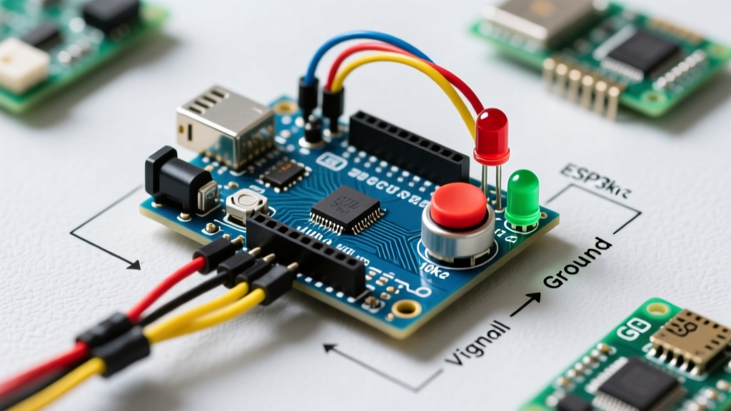

The Anatomy of an Arduino Push Button LED Circuit
Building a reliable arduino push button led circuit seems like the most basic rite of passage for microcontroller enthusiasts. However, mismatched logic levels, floating digital pins, and incorrect current limiting cause over 90% of beginner and intermediate project failures. In 2026, with the widespread adoption of 3.3V logic boards like the Arduino Nano ESP32 and the continued dominance of 5V classics like the Uno R4 Minima, understanding component compatibility is more critical than ever.
This comprehensive compatibility guide breaks down the exact hardware specifications, wiring topologies, and logic requirements to ensure your switch inputs and LED outputs operate flawlessly without damaging your microcontroller.
Microcontroller Logic Level Compatibility
The first point of failure in any digital input/output setup is ignoring the board's native logic voltage. Push buttons themselves are logic-agnostic—they are simply mechanical conductors. However, the way the microcontroller reads the button and drives the LED is strictly bound by its VCC.
5V Logic Boards (Arduino Uno R3, Uno R4 Minima, Mega 2560)
- Thresholds: Recognizes anything above ~3.0V as HIGH and below ~1.5V as LOW.
- LED Compatibility: Can easily drive standard 5mm through-hole LEDs with a simple series resistor.
- Current Limits: Absolute maximum of 40mA per I/O pin (20mA recommended for continuous operation).
3.3V Logic Boards (Arduino Nano 33 IoT, Nano ESP32, Portenta C33)
- Thresholds: Recognizes anything above ~2.0V as HIGH.
- LED Compatibility: Requires lower-value current-limiting resistors. Some high-forward-voltage LEDs (like certain blues and whites) will not illuminate properly on a 3.3V pin without a transistor driver.
- Current Limits: Often strictly limited to 12mA to 16mA per pin. Exceeding this will permanently degrade the silicon.
Expert Warning: Never connect a 5V external pull-up resistor network to a 3.3V microcontroller pin. When the button is released, the pin will be subjected to 5V, which will fry the input protection diodes on 3.3V ESP32-based Arduino boards.
Push Button Switch Specifications & Selection
Not all switches are created equal. When selecting a switch for your microcontroller input, you must consider mechanical travel, contact rating, and internal resistance.
Tactile Switches (e.g., C&K PTS645 Series)
These are the standard 6x6mm momentary switches found in most starter kits. They are rated for 50mA at 12V DC. Because an Arduino digital input draws less than 1µA (microamp) of leakage current, these switches will theoretically last indefinitely in logic-level applications. However, their internal contact resistance can fluctuate between 10mΩ and 100mΩ during actuation, which contributes to contact bounce.
Panel Mount Momentary Switches (e.g., Honeywell Micro Switch)
For industrial or permanent enclosures, panel mount switches offer higher current ratings (often 5A+). While overkill for logic signals, their heavier physical contacts generally exhibit less severe high-frequency bounce than cheap tactile switches, making software debouncing more predictable.
LED Forward Voltage & Resistor Compatibility Matrix
Driving an LED directly from an Arduino pin without a current-limiting resistor will draw excessive current, dimming the LED over time and potentially destroying the microcontroller's ATmega or ESP32 GPIO bank. You must calculate the resistor based on the specific LED color and your board's logic voltage.
| LED Color | Typical Forward Voltage (Vf) | Target Current (If) | Resistor for 5V Board | Resistor for 3.3V Board |
|---|---|---|---|---|
| Red (Standard 5mm) | 2.0V | 20mA | 150Ω | 68Ω |
| Yellow / Green | 2.1V | 20mA | 150Ω | 62Ω |
| Blue / White | 3.2V | 20mA | 90Ω | Not Recommended* |
*Note: Blue and White LEDs require a Vf close to or exceeding 3.3V. On a 3.3V board, the voltage drop across the LED leaves almost zero headroom for a current-limiting resistor, resulting in unpredictable brightness and potential thermal runaway. Use a low-side NPN transistor (like a 2N2222) for these LEDs on 3.3V boards.
Solving the Floating Pin Problem: Pull-Up vs. Pull-Down
A push button connects a digital pin to either VCC or GND when pressed. When released, the pin is left "floating"—disconnected from any defined voltage. A floating pin acts as an antenna, picking up electromagnetic interference (EMI) and causing the LED to flicker randomly.
External Pull-Down Resistor Topology
In this setup, a 10kΩ resistor ties the digital pin to GND. The button connects the pin to VCC (5V or 3.3V) when pressed.
- Logic State: Reads LOW when idle, HIGH when pressed.
- Compatibility: Universally compatible with all Arduino boards, but requires extra breadboard wiring and an additional component.
Internal Pull-Up Resistor Topology (Recommended)
Modern microcontrollers feature built-in pull-up resistors (typically 20kΩ to 50kΩ) that can be enabled via software. According to the official Arduino InputPullup documentation, this eliminates the need for external resistors on the switch side.
- Wiring: One side of the button to GND, the other to the digital pin.
- Logic State: Reads HIGH when idle, LOW when pressed (Inverted logic).
- Code Implementation: Use
pinMode(buttonPin, INPUT_PULLUP);
Debouncing: Hardware vs. Software Compatibility
Mechanical switch contacts physically bounce when they collide, creating a rapid series of HIGH/LOW transitions lasting anywhere from 1ms to 50ms. If your code simply reads digitalRead() in a fast loop, a single button press will toggle your LED dozens of times.
Hardware Debouncing (RC Filter)
Placing a 100nF ceramic capacitor in parallel with the switch, or between the digital pin and GND, creates a low-pass filter. This physically smooths the voltage transition. While effective, it adds component cost and board space, and can slow down the maximum actuation rate of the button.
Software Debouncing (The 2026 Standard)
For 99% of maker projects, software debouncing is the superior choice. The industry-standard library for this is Bounce2 by Thomas Ouellet Fredericks. Bounce2 is highly optimized, non-blocking, and compatible with virtually every Arduino architecture, from AVR to ARM Cortex-M4.
By implementing Bounce2, you can reliably detect exact button press durations, filter out EMI noise, and maintain precise LED state toggling without relying on the blocking delay() function.
Real-World Troubleshooting & Edge Cases
Even with perfect wiring, edge cases can derail your project. Here is how to diagnose the most common anomalies:
1. The LED Glows Dimly When 'Off'
Cause: You are likely using an external pull-down resistor with a value that is too high (e.g., 1MΩ), or you have a long wire run acting as a capacitor. Alternatively, if using an internal pull-up, you might have accidentally configured the pin as OUTPUT and written it LOW, creating a short through the LED.
Fix: Verify pin modes. Ensure external pull-downs are 10kΩ, not 1MΩ. For long wire runs, refer to SparkFun's guide on pull-up resistors to understand how wire capacitance affects signal rise times.
2. The LED State Toggles Multiple Times per Press
Cause: Switch bounce or electromagnetic interference from nearby motors/relays.
Fix: Increase the debounce interval in your Bounce2 configuration from the default 10ms to 25ms or 50ms. If the issue persists, route your switch wires away from inductive loads and add a 100nF decoupling capacitor directly across the switch terminals.
3. Microcontroller Resets When Button is Pressed
Cause: A short circuit in the wiring, or the button is accidentally wired to the RESET pin instead of a standard GPIO pin, pulling the reset line low.
Fix: Check your physical pinout mapping. Ensure the button is connected to a standard digital I/O pin (e.g., D2 through D12 on an Uno) and not the dedicated hardware reset or chip-select pins.
Summary Checklist for Flawless Integration
- Verify Board Voltage: Confirm if your board is 5V or 3.3V before selecting LED resistors.
- Use INPUT_PULLUP: Wire the button between GND and the digital pin to save components and reduce noise susceptibility.
- Calculate Exact Ohms: Never guess LED resistor values; use the Vf matrix provided above.
- Implement Bounce2: Abandon
delay()based debouncing for non-blocking, professional-grade state management. - Protect 3.3V Pins: Use transistor drivers for high-current or high-Vf LEDs when working with modern ESP32-based Arduino boards.
By treating the humble push button and LED not as trivial toys, but as precise electromechanical components requiring proper impedance matching and logic-level respect, your projects will achieve industrial-grade reliability.