
The Shift to Sub-45mm Microcontrollers
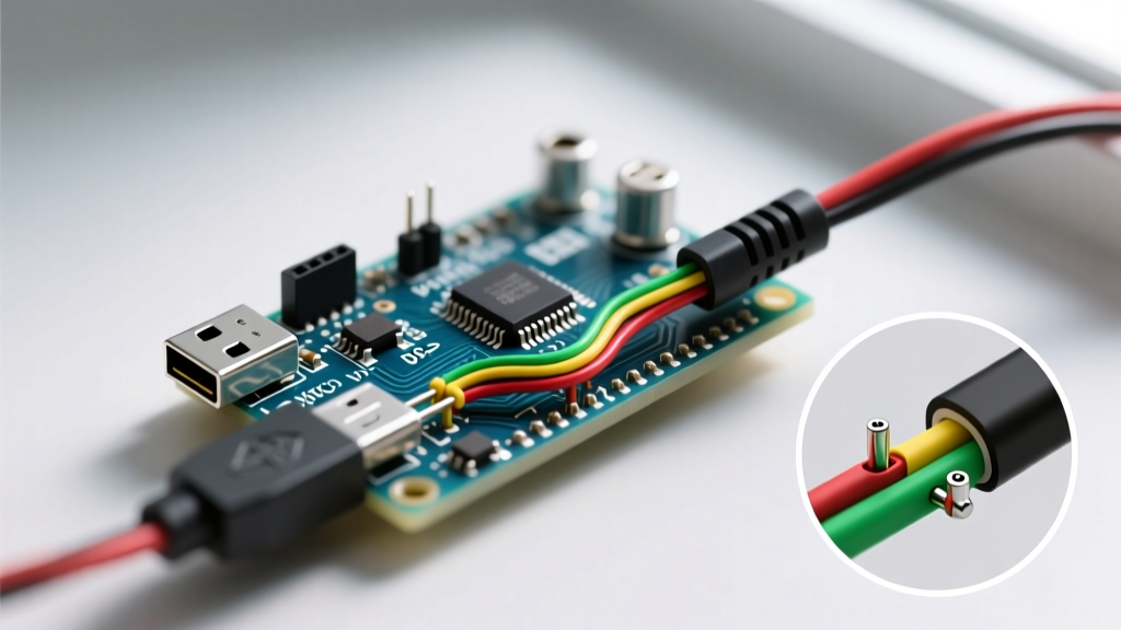
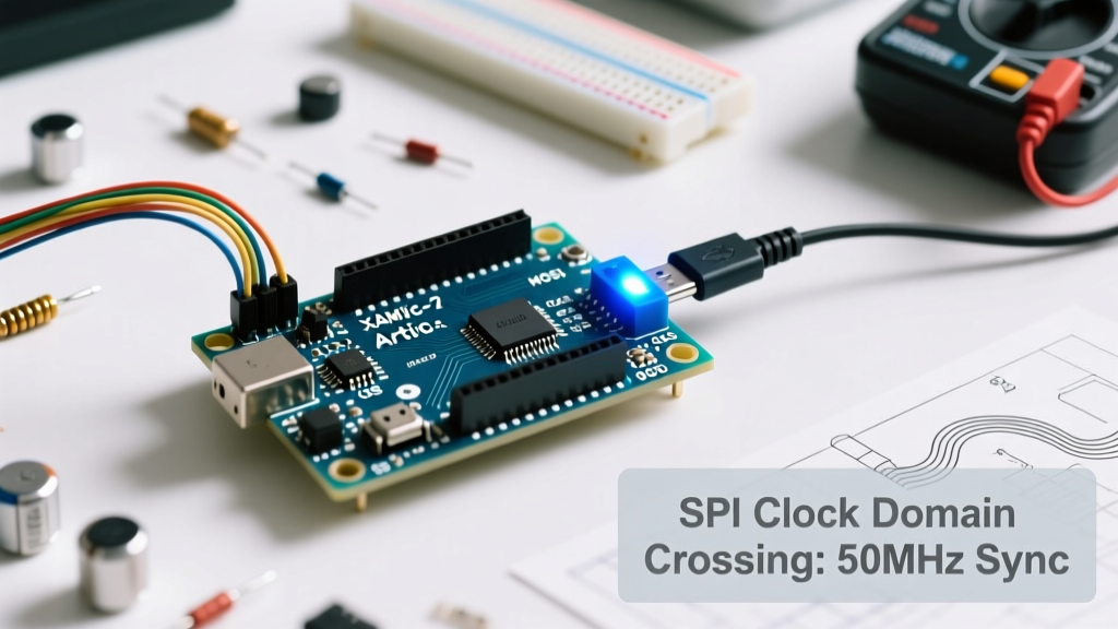
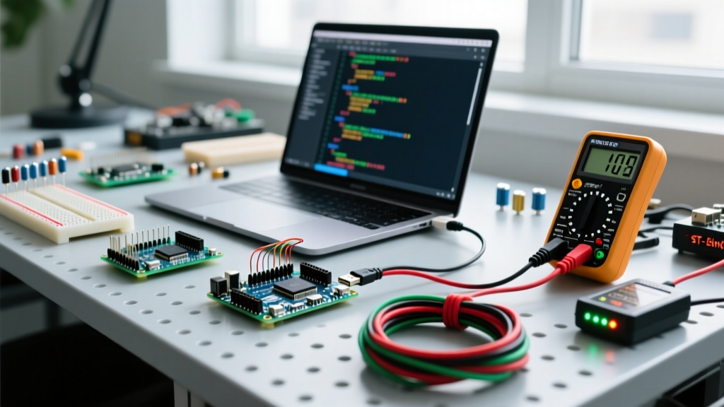
When makers transition from prototyping on a workbench to deploying permanent installations, the standard 68.6 x 53.4 mm Arduino Uno becomes a spatial and electrical liability. This is where small Arduino boards become essential. By stripping away redundant components like the barrel jack, bulky DIP sockets, and oversized USB-B connectors, engineers have compressed the core microcontroller architecture into footprints smaller than a postage stamp.
However, shrinking the board introduces complex engineering trade-offs. You lose onboard voltage regulation headroom, swap 5V logic for 3.3V sensitivity, and change how the bootloader communicates over USB. In 2026, the market for compact development boards is dominated by three distinct architectural lineages: the legacy 5V DIP-30 footprint (Nano/Micro), the native-USB HID boards, and the ultra-compact castellated-edge IoT modules (like the Seeed XIAO series). Understanding the silicon-level differences between these form factors is critical to preventing hardware destruction and ensuring sketch stability.
Form Factor and Silicon Comparison Matrix
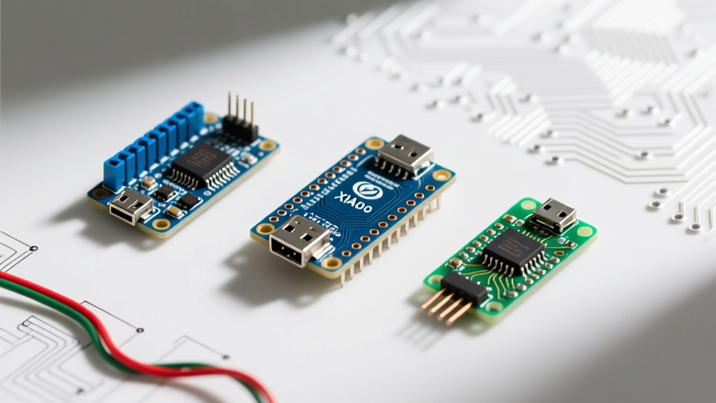
Choosing the right compact board requires looking past the physical dimensions and examining the underlying System-on-Chip (SoC) or microcontroller unit (MCU). Below is a technical breakdown of the three most prominent small Arduino boards used in modern DIY and commercial prototyping.
| Board Model | Core MCU | Dimensions | Logic Level | Flash / RAM | Est. Price (2026) | Primary Use Case |
|---|---|---|---|---|---|---|
| Arduino Nano Every | ATmega4809 | 45 x 18 mm | 5V | 48KB / 6KB | $12.50 | Legacy 5V sensor integration, tight breadboarding |
| Arduino Micro | ATmega32U4 | 48 x 18 mm | 5V | 32KB / 2.5KB | $22.00 | Native USB HID (Keyboards, Mice, MIDI controllers) |
| Seeed XIAO ESP32S3 | ESP32-S3 (Dual-core) | 21 x 17.5 mm | 3.3V | 8MB / 512KB + PSRAM | $15.99 | Battery IoT, Edge AI, Camera integration |
While the Nano Every and Micro maintain the classic 15-pin DIP footprint—making them drop-in replacements for decades of breadboard layouts—the Seeed XIAO ESP32S3 utilizes a stamped-edge design with castellated holes. This allows the XIAO to be surface-mounted (SMD) directly onto a custom PCB without requiring bulky pin headers, a massive advantage for permanent, high-vibration installations like drone avionics or automotive telemetry.
The 5V vs. 3.3V Logic Level Trap
The most common failure mode when migrating to modern small Arduino boards is ignoring logic level thresholds. The Arduino Micro and Nano Every operate at 5V logic. In the ATmega architecture, a logic HIGH (V_IH) is recognized at roughly 3V, and the pins can tolerate up to 5.5V without damage.
Conversely, modern compact powerhouses like the XIAO ESP32S3 or the Arduino Nano 33 IoT operate strictly at 3.3V. The ESP32-S3 GPIO pins have an absolute maximum voltage rating of 3.6V.
Real-World Failure Scenario: The HC-SR04 Ultrasonic Sensor
Imagine you are building a compact robotic rover using a XIAO ESP32S3 and a standard HC-SR04 ultrasonic distance sensor. The HC-SR04 requires 5V to operate its transducers and outputs a 5V echo pulse. If you wire the Echo pin directly to the XIAO's GPIO 2:
- The Result: You will force 5V into a 3.3V-tolerant pin.
- The Damage: This triggers a parasitic latch-up effect inside the ESP32-S3 silicon, drawing excessive current and permanently frying the GPIO pad or the entire MCU within milliseconds.
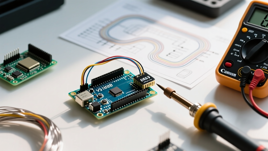
Expert Fix: Always use a voltage divider for 5V-to-3.3V digital signals. For the HC-SR04 Echo pin, solder a 1kΩ resistor in series with the signal line, and a 2kΩ resistor pulling the GPIO side to ground. This safely steps the 5V pulse down to ~3.33V, well within the ESP32's safe V_IH threshold of 2.3V.
Native USB vs. UART Bridges: Upload Troubleshooting
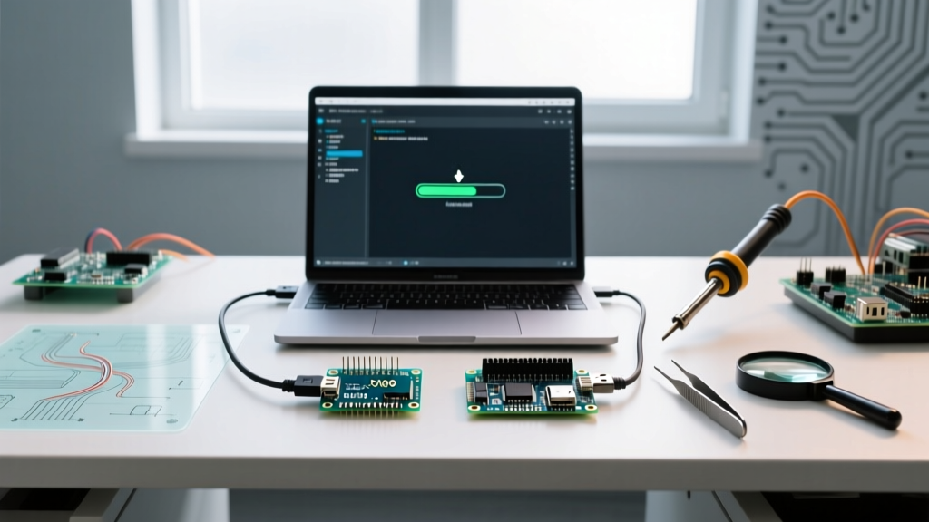
Small Arduino boards handle serial communication and sketch uploading in two fundamentally different ways, which drastically affects how you troubleshoot compilation and upload errors in the Arduino IDE.
1. The UART Bridge Method (Arduino Nano Every / Clones)
Boards like the Nano Every use a dedicated secondary chip (such as the CH340 or FT232RL) to act as a USB-to-UART bridge. The main MCU (ATmega4809) communicates with this bridge via hardware serial pins (TX/RX). The Advantage: The USB connection is entirely independent of your sketch. Even if your code crashes or enters an infinite loop, the COM port remains visible in your operating system, and the IDE can always force a reset via the DTR (Data Terminal Ready) signal line.
2. The Native USB Method (Arduino Micro / XIAO ESP32S3)
Boards featuring the ATmega32U4 or ESP32-S3 handle USB communication directly on the main processor. There is no secondary bridge chip. This saves board space and reduces BOM costs, but it introduces a critical vulnerability: your sketch controls the USB stack.
If you write a sketch that blocks the main loop, disables interrupts, or crashes the MCU before the USB stack initializes, the board will disappear from your computer's device manager. The IDE will throw a 'Port not found' or 'Upload timeout' error.
The 1200bps Recovery Protocol: To recover a 'bricked' native USB board, you must manually trigger the bootloader. Plug the board into your PC, locate the tiny tactile reset button on the PCB, and double-tap it quickly. This forces the MCU to reboot into the bootloader, which enumerates as a new COM port at exactly 1200 baud. You have roughly 3 seconds to click 'Upload' in the IDE before the bootloader times out and returns to the crashed sketch. For deeper insights into native USB architectures, refer to the official Arduino Micro hardware documentation.
Power Delivery and LDO Bypass Strategies
Thermal management is severely constrained on small Arduino boards due to the lack of copper pour area and ground planes. This makes power routing a critical design consideration.
Most 5V small boards include an onboard Low Dropout Regulator (LDO), such as the NCP1117, to step down external power to 5V. If you connect a 9V battery to the VIN pin of an Arduino Micro, the LDO must dissipate the 4V difference as heat. Because the PCB is only 18mm wide, the LDO will thermally throttle or shut down if your sketch draws more than ~150mA of continuous current (e.g., driving a strip of WS2812B NeoPixels).
Actionable Power Routing Rules:
- Bypass the LDO for High Current: If your project requires more than 100mA, do not use the VIN pin. Instead, supply a regulated 5V directly to the '5V' pin. This bypasses the onboard LDO entirely, eliminating the thermal bottleneck.
- Lithium-Ion Integration: For 3.3V boards like the XIAO, never feed 4.2V (a fully charged Li-Po cell) into the 3.3V pin. While 4.2V might seem close to 3.3V, it exceeds the absolute maximum ratings of the ESP32-S3 core. Use a dedicated 3.3V LDO module (like the HT7333) or a buck-boost converter between the battery and the board's 3.3V input.
- Deep Sleep Current: When designing battery-operated nodes, note that the onboard power LEDs on small boards can draw 5mA to 10mA continuously. On a 200mAh Li-Po battery, the LED alone will drain the cell in 20 hours. Desolder the power LED or use a board variant that allows software-controlled LED disabling to achieve true microamp-level deep sleep currents.
Summary: Selecting the Right Footprint
The ecosystem of small Arduino boards has matured far beyond simply shrinking the Uno. If your project relies on legacy 5V industrial sensors and requires robust, crash-proof serial uploading, the Arduino Nano Every remains the undisputed workhorse. If you are building custom macro-pads or MIDI controllers requiring native HID capabilities, the ATmega32U4-based Micro is mandatory. However, if your 2026 project demands Wi-Fi, BLE, edge-machine learning, and a footprint smaller than a coin, transitioning to 3.3V castellated boards like the XIAO ESP32S3 is the only logical path—provided you respect the strict logic-level and power-delivery constraints of modern silicon.