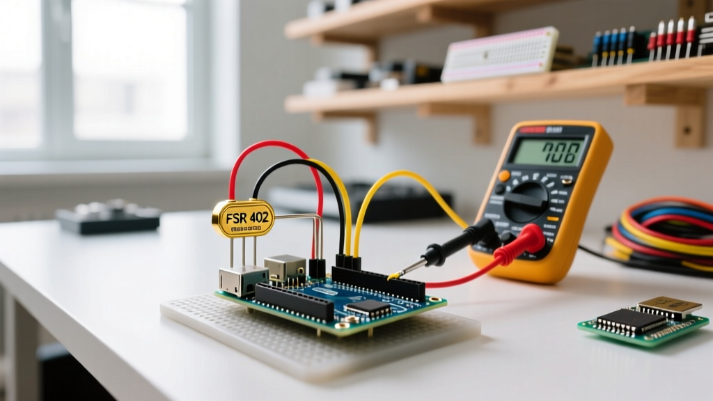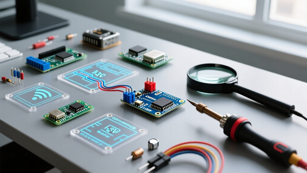

The 2026 Landscape of Arduino Accessories
The maker ecosystem has evolved dramatically over the last few years. While the classic 5V ATmega328P-based boards remain popular, the market in 2026 is heavily dominated by 32-bit architectures like the Renesas RA4M1 (found in the Arduino Uno R4 WiFi) and the ESP32-S3 (found in the Nano ESP32). This architectural shift has created a massive compatibility divide. When sourcing arduino accessories—ranging from motor shields and I2C sensor breakout boards to TFT displays and relay modules—makers frequently encounter logic-level mismatches, power delivery failures, and mechanical misalignments.
This comprehensive compatibility guide cuts through the marketing fluff. We will explore exact voltage tolerances, I2C bus capacitance limits, and thermal failure modes of onboard voltage regulators, ensuring your next project doesn't end in a fried microcontroller or silent communication failures.
Logic Level Compatibility: The 5V vs. 3.3V Divide
The most common point of failure when integrating new arduino accessories into modern projects is logic voltage mismatching. Classic Arduino shields and sensors were designed for 5V logic HIGH thresholds. Modern boards like the Nano ESP32 or Seeed Studio XIAO operate strictly at 3.3V.
CRITICAL WARNING: Connecting a 5V output from a classic shield directly to a 3.3V GPIO pin on a Nano ESP32 will exceed the absolute maximum ratings of the ESP32-S3 silicon, causing permanent latch-up or thermal destruction of the microcontroller's input protection diodes.
Solving Logic Mismatches with Level Shifters
To bridge the gap between 5V accessories and 3.3V microcontrollers, you must use a bidirectional logic level converter. The industry standard for this is the BSS138 N-Channel MOSFET based level shifter.
- Cost: $1.20 to $2.50 per 4-channel module in 2026.
- Speed: Capable of handling I2C standard mode (100 kHz) and fast mode (400 kHz) without signal degradation.
- Wiring: Connect LV to 3.3V, HV to 5V, and tie both grounds together. For a deep dive into the physics of MOSFET-based translation, refer to the SparkFun Logic Levels Tutorial.
Edge Case: Some modern 5V boards, like the Uno R4, feature 5V-tolerant I/O pins despite running on a 3.3V internal core. However, relying on 5V tolerance for high-speed SPI communication can lead to edge-case timing errors due to internal clamping diode capacitance. Always use a dedicated level shifter for SPI buses exceeding 10 MHz.
Form Factor & Pinout Matrix: R3 vs. R4 vs. Nano
Mechanical compatibility is just as crucial as electrical compatibility. The 'R3' standard dictates specific mounting hole placements and header spacing, but newer boards have introduced subtle deviations.
| Board Model | Logic Voltage | Vin Range | R3 Shield Fitment | Notable Quirks & Edge Cases |
|---|---|---|---|---|
| Uno R3 (Classic) | 5V | 7-12V | 100% Native | I2C duplicated on A4/A5. ISP header is standard 2x3. |
| Uno R4 Minima/WiFi | 5V (Tolerant) | 6-24V | 95% Compatible | Added SWD header. USB-C replaces Type-B. 5V pin output limited to 1.5A. |
| Nano ESP32 | 3.3V | 5-18V | Nano Footprint | Castellated pads. 3.3V logic requires shifters for 5V shields. B2 pin mapped to BOOT. |
| Mega 2560 R3 | 5V | 7-12V | R3 + Extended | I2C is on pins 20/21, NOT A4/A5. Shields hardcoding A4/A5 for I2C will fail. |
Communication Protocol Pitfalls: I2C Bus Capacitance
When daisy-chaining multiple I2C-based arduino accessories (e.g., three BME280 environmental sensors, two SSD1306 OLEDs, and an MPU6050 IMU), makers often experience random data corruption or complete bus lockups. This is rarely a software issue; it is a hardware limitation defined by the NXP I2C-bus specification.
The 400pF Capacitance Limit
The I2C protocol relies on open-drain outputs and external pull-up resistors. The total capacitance of the bus (wires, traces, and sensor pins) must not exceed 400 pF. Standard dupont wires add roughly 20-30 pF per foot. If you exceed this limit, the RC time constant of the pull-up resistor and bus capacitance becomes too large, causing the signal to miss the setup/hold times required by the microcontroller.
Actionable Solutions for High-Capacitance Buses:
- Lower the Pull-Up Resistance: Drop from the standard 4.7kΩ to 2.2kΩ or 1kΩ. This increases current draw (up to 3mA per line) but sharpens the rising edge of the signal.
- Active Pull-Ups: Use an LTC4311 I2C bus extender IC. It actively sources current during the rising edge, effectively eliminating the RC delay without violating I2C current sink limits.
- I2C Multiplexers: The TCA9548A allows you to split the bus into 8 isolated segments, keeping the capacitance of each segment well under the 400 pF threshold while also resolving I2C address conflicts.
Power Delivery: Sizing Your Arduino Accessories
A frequent cause of erratic behavior and spontaneous resets in complex builds is inadequate power delivery, specifically regarding the onboard linear voltage regulators found on budget-friendly clone boards.
The AMS1117 Thermal Trap
Most classic Nano and Uno clones utilize the AMS1117-5.0 linear voltage regulator in a SOT-223 package to step down voltage from the barrel jack or Vin pin. Linear regulators dissipate excess voltage as heat. The formula for power dissipation is:
P = (Vin - Vout) × I
If you connect a 12V power supply to Vin and your arduino accessories (like a servo shield or a string of NeoPixels) draw just 400mA from the 5V pin, the regulator must dissipate (12V - 5V) × 0.4A = 2.8 Watts. The SOT-223 package has a junction-to-ambient thermal resistance of roughly 50°C/W without a dedicated heatsink. This results in a temperature rise of 140°C above ambient. The AMS1117 will hit its internal thermal shutdown threshold (typically 165°C) almost instantly, causing the microcontroller to brown out and reset continuously.
The 2026 Best Practice: Never power high-current accessories (anything exceeding 150mA) through the board's linear regulator. Instead, use an external switching buck converter (such as the MP2307 or LM2596 module, costing around $1.80). Step your main 12V or 24V supply down to 5V using the buck converter, and feed that 5V directly into the microcontroller's 5V pin (bypassing the onboard regulator entirely).
Essential Compatibility Checklist Before You Buy
Before adding new arduino accessories to your cart, run through this rapid diagnostic checklist:
- Logic Thresholds: Does the accessory require 5V HIGH to trigger (e.g., older HC-SR04 ultrasonic sensors), and is your MCU 3.3V?
- Power Draw: What is the peak current? If it exceeds 200mA, plan for an external buck converter.
- I2C Pull-Ups: Do the breakout boards have onboard 4.7kΩ pull-ups? If you have more than three devices on the bus, you may need to scrape off the 0603 resistors to prevent the parallel resistance from pulling the bus too low (below 3mA sink limit).
- SPI Chip Select (CS): Does the shield hardcode the CS pin to D10? If you are stacking multiple SPI shields, ensure you can physically cut the trace and reroute the CS pin to a different GPIO.
Frequently Asked Questions
Can I use a classic 5V relay module on a Nano ESP32?
Most 5V relay modules use an optocoupler (like the PC817) driven by an NPN transistor. The 3.3V GPIO output of the Nano ESP32 is usually sufficient to trigger the transistor base, provided the module has a low-forward-voltage LED inside the optocoupler. However, you must power the relay module's VCC from a 5V source, not the ESP32's 3.3V pin. For guaranteed reliability, use a relay module specifically rated for 3.3V logic, which typically features a MOSFET driver instead of a BJT.
Why does my TFT shield work on the Uno R3 but show a white screen on the Uno R4?
Many older TFT shields utilize the 8-bit parallel interface and rely on direct port manipulation (e.g., writing directly to the PORTD or PORTB registers of the ATmega328P). The Uno R4 uses a Renesas ARM Cortex-M4 processor, which has an entirely different memory map and register structure. Libraries that use hardcoded AVR port manipulation will fail silently or crash on the R4. You must ensure the TFT library (like MCUFRIEND_kbv or Adafruit_GFX) has been explicitly updated to support the Renesas RA4M1 architecture via hardware abstraction layers (HAL).
Are all USB-C cables compatible with the Uno R4 and Nano ESP32?
No. In 2026, the market is flooded with USB-C cables wired exclusively for power delivery (missing the D+ and D- data lines). Furthermore, some USB-C to USB-C cables lack the 5.1kΩ pull-down resistors on the connector required to trigger power delivery from a modern USB-C PD wall charger. Always use a certified data-sync USB-C cable with proper CC pin termination to ensure your PC recognizes the serial port and the board receives adequate current.