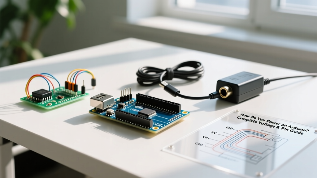

The Core Question: How Do You Power an Arduino Safely?
If you are wondering how do you power an Arduino without accidentally frying the microcontroller or triggering a thermal shutdown, you are asking the right question. Power management is the most common failure point for beginners and intermediate makers alike. While the Arduino platform is famously forgiving, misunderstanding the onboard power architecture—specifically the difference between linear regulators, switching buck converters, and direct pin injection—will inevitably lead to melted components, brownout reset loops, or dead boards.
In this concept explainer, we will dissect the exact power pathways of the most popular boards (including the critical architectural shifts in the newer Arduino Uno R4 series), calculate thermal dissipation limits, and provide a definitive guide to choosing the right power source for your specific project.
The Anatomy of Arduino Power Architecture
To understand how to power the board, you must first understand what happens to the electricity once it enters the PCB. The power routing depends heavily on which generation of the board you are using.
The Classic Linear Regulator (Uno R3, Nano, Mega)
Legacy boards like the Arduino Uno R3 and its millions of clones rely on a linear voltage regulator (typically the NCP1117ST50T3G or the AMS1117-5.0) to step down higher input voltages to a stable 5V. Linear regulators work by burning off excess voltage as heat. According to the Texas Instruments LM1117 datasheet and similar linear regulator specifications, these components have strict thermal limits. The TO-223 SMD package commonly used on these boards has a junction-to-ambient thermal resistance of roughly 50°C/W without a heatsink.
The Modern Switching Regulator (Uno R4 Minima/WiFi)
The release of the Arduino Uno R4 series fundamentally changed the power rules. The R4 boards utilize a high-efficiency switching buck converter instead of a linear regulator. This means you can safely draw up to 1.5A from the 5V rail without the board overheating, a massive upgrade for powering small sensors, displays, and low-draw actuators directly from the board.
The 4 Methods to Power an Arduino
When evaluating how do you power an Arduino for a specific deployment, you have four primary entry points. Each carries distinct voltage requirements, current limits, and risk profiles.
1. USB Power (The Safest Baseline)
Plugging into a standard USB port (Type-B on the R3, Type-C on the R4) provides a regulated 5V directly to the board's 5V rail. The USB line is protected by a resettable PTC polyfuse (usually rated at 500mA). If your project draws more than 500mA, the polyfuse will heat up, increase its resistance, and drop the voltage, effectively protecting your computer's USB port from damage. Best for: Desktop prototyping, low-power sensor logging, and serial communication.
2. The Barrel Jack (DC 2.1mm)
The barrel jack accepts unregulated DC power and routes it through a polarity protection diode before hitting the onboard voltage regulator. The official Arduino Power Supplies Guide recommends an input voltage between 7V and 12V. While the board can technically survive up to 20V, doing so will cause the linear regulator to overheat almost instantly under any meaningful load.
3. The Vin Pin (Direct to Regulator)
The Vin (Voltage In) pin is electrically connected to the barrel jack's output, bypassing the polarity protection diode. This is highly useful for custom PCB shields or battery packs. Because you bypass the diode, you avoid the ~0.7V voltage drop, meaning a 7V battery pack will actually reach the regulator as 7V, not 6.3V. Warning: Vin has no reverse polarity protection. Swapping positive and negative wires will instantly destroy the regulator.
4. The 5V Pin (Direct Injection)
Critical Warning: Injecting power directly into the 5V pin completely bypasses the onboard voltage regulator and the polyfuse. If you supply 5.1V, you might survive. If you accidentally supply 9V or reverse the polarity, the ATmega328P (or RA4M1 on the R4) will be permanently destroyed in milliseconds.
Use the 5V pin only when you have a highly regulated, clean 5V external power supply (like a dedicated USB power bank wired directly, or a high-quality buck converter).
Thermal Math: Why 12V Power Supplies Destroy Linear Regulators
The most common mistake makers make when figuring out how do you power an Arduino is using a 12V wall adapter via the barrel jack to power the board alongside a few servos or LEDs. Let us look at the thermal dissipation math for a classic Uno R3 with an AMS1117 linear regulator.
The formula for power dissipated as heat is: P = (V_in - V_out) × I_load
| Input Voltage (Vin) | Load Current (I) | Heat Dissipated (Watts) | Est. Temp Rise (°C) | Result / Board State |
|---|---|---|---|---|
| 7V (Recommended Min) | 100 mA | 0.2W | +10°C | Safe (Runs cool) |
| 9V (Standard Adapter) | 200 mA | 0.8W | +40°C | Warm (Safe, ~65°C total) |
| 12V (High Voltage) | 150 mA | 1.05W | +52.5°C | Hot (Approaching limits) |
| 12V (With Servo/LEDs) | 300 mA | 2.1W | +105°C | Thermal Shutdown (125°C+) |
As the table demonstrates, pulling just 300mA from a 12V source generates over 2 watts of heat. The SMD regulator will hit its internal thermal shutdown threshold (usually around 125°C), causing the Arduino to constantly reboot—a phenomenon known as a brownout reset loop.
Real-World Failure Modes & Edge Cases
The WS2812B NeoPixel Trap
A standard WS2812B RGB LED draws roughly 60mA at peak white brightness. A strip of just 20 LEDs requires 1.2A. If you attempt to power this strip from the Arduino's 5V pin while using a 9V barrel jack, the linear regulator will attempt to dissipate (9V - 5V) × 1.2A = 4.8 Watts. The regulator will literally desolder itself from the PCB or vent magic smoke within seconds. Solution: Power high-draw LEDs directly from a dedicated 5V power supply, tying only the data line and ground to the Arduino.
Servo Motor Brownouts
Standard micro servos (like the SG90) draw ~200mA, but larger metal-gear servos (like the MG996R) can spike to 2.5A during stall conditions. The Arduino's onboard 5V rail cannot supply this. When the servo spikes, the 5V rail sags below the ATmega328P's brownout detection threshold (typically 4.3V or 2.7V depending on fuse settings), causing the microcontroller to reset and the servo to jitter wildly.
Best Practices for High-Current Projects
If your project requires more than 400mA of continuous 5V current, you must abandon the Arduino's onboard linear regulator entirely. The industry-standard approach for robotics and kinetic art is to use an external UBEC (Universal Battery Elimination Circuit) or a dedicated switching step-down (buck) converter.
- Component Recommendation: The Pololu 5V, 5A Step-Down Voltage Regulator D24V50F5 (priced around $9.50) is a highly efficient buck converter that can accept up to 38V input and output a rock-solid 5V at 5A.
- Wiring Strategy: Wire your high-capacity battery (e.g., a 3S 11.1V LiPo) directly into the Pololu buck converter. Wire the 5V output of the converter to the Arduino's 5V pin (bypassing the weak onboard regulator) and wire the high-current loads (servos, steppers, LEDs) directly to the converter's output terminals.
- Grounding: Always ensure the ground (GND) of the external power supply is tied directly to the Arduino's GND pin. Without a common ground reference, digital logic signals will float, leading to erratic behavior or damaged I/O pins.
Summary: Choosing Your Power Path
Understanding how do you power an Arduino comes down to respecting the physical limits of the onboard components. Use USB for safe, low-power prototyping. Use the barrel jack or Vin (7V-9V) for standalone deployments with minimal onboard current draw. For anything involving motors, high-density LED strips, or heavy sensor arrays, bypass the internal regulation entirely and inject clean 5V from a high-quality external switching regulator. By matching your power topology to your project's actual current demands, you ensure long-term reliability and protect your hardware from catastrophic thermal failure.