
The Architecture of Arduino Power Delivery
Configuring arduino power correctly is the difference between a reliable embedded system and a fried ATmega328P microcontroller. Whether you are building a low-power remote environmental sensor or a high-torque robotic actuator, understanding the physical limits of the onboard power tree is non-negotiable. Many makers treat power delivery as an afterthought, leading to mysterious brownout resets, erratic sensor readings, or the dreaded 'magic smoke' failure.
In this configuration guide, we dissect the exact electrical pathways, voltage regulator thermal limits, and wiring topologies required to safely power your Arduino projects in 2026 and beyond.
The Input Matrix: USB vs. Barrel Jack vs. VIN
The standard Arduino Uno R3 and its modern successors offer three primary methods for accepting external power. Each path routes through different protection circuits and voltage regulators.
| Input Method | Voltage Range | Max Safe Current | Protection Circuitry | Best Use Case |
|---|---|---|---|---|
| USB Type-B / Type-C | 4.75V - 5.25V | 500mA (USB 2.0) | 500mA PTC Resettable Polyfuse | Desktop programming, low-power logic |
| DC Barrel Jack | 7V - 12V (Rec) | ~800mA (Thermal limited) | Reverse polarity diode (1N4007) | Standalone projects, moderate loads |
| VIN Pin | 7V - 12V (Rec) | ~800mA (Thermal limited) | None (Direct to regulator) | Custom PCBs, battery packs |
| 5V Pin (Direct) | 4.8V - 5.2V | Board trace limit (~1A) | None (Bypasses regulator) | High-current external buck converters |
Expert Warning: Never backfeed 5V into the 5V pin while the USB cable is connected. The Arduino Uno lacks an active hardware multiplexer to isolate the USB 5V rail from the 5V header pin. Forcing 5.1V from an external supply into the 5V pin while the PC supplies 4.9V via USB will cause current to flow backward through the USB polyfuse, potentially damaging your computer's motherboard.
Deep Dive: The Linear Regulator Thermal Bottleneck
When you supply power via the Barrel Jack or VIN pin, the voltage is routed through an onboard linear regulator. On the classic Uno R3, this is typically the NCP1117ST50T3G (a 5V, 1A linear regulator in a SOT-223 package). According to the ON Semiconductor NCP1117 Datasheet, this component requires a minimum dropout voltage of 1.1V, meaning you must supply at least 6.1V to achieve a stable 5V output.
The Thermal Shutdown Math
Linear regulators operate by burning excess voltage as heat. The power dissipated ($P_D$) is calculated as:
P_D = (V_IN - V_OUT) * I_LOAD
Consider a scenario where you power your Arduino with a 12V wall adapter and draw 400mA to power an LCD screen and a few LEDs:
- V_IN: 12V
- V_OUT: 5V
- I_LOAD: 0.4A
- P_D: (12 - 5) * 0.4 = 2.8 Watts
The SOT-223 package has a junction-to-ambient thermal resistance ($R_{\theta JA}$) of roughly 50°C/W without a heatsink. A 2.8W dissipation results in a temperature rise of 140°C above ambient. If your room is 25°C, the regulator junction hits 165°C, instantly triggering the internal thermal shutdown. Your Arduino will reboot endlessly.
Configuration Rule: If your project draws more than 150mA total, do not use the barrel jack with a 12V supply. Either drop your input voltage to 7.5V, or bypass the onboard regulator entirely using an external switching buck converter.
USB Polyfuse and Brownout Failures
The USB power path is protected by a resettable PTC polyfuse (often a Bourns MF-MSMF050-2). This fuse is rated to trip at 500mA. However, the trip curve is time-dependent. If you connect a standard micro servo (like the SG90) directly to the Arduino's 5V pin and command it to move under load, the stall current can spike to 700mA.
Before the polyfuse physically trips, its internal resistance increases dramatically. This resistance causes a voltage drop across the fuse. The 5V rail might sag to 3.8V, which is below the Brown-Out Detection (BOD) threshold of the ATmega328P (typically set to 4.3V or 2.7V depending on the fuse bits). The microcontroller will reset, the servo stops, the polyfuse cools, and the cycle repeats. This manifests as a 'twitching' servo and a blinking pin 13 LED.
For comprehensive USB power specifications and protection topologies, refer to the Arduino Official Power Supply Documentation.
High-Current Actuator Configurations (Motors & Servos)
A fundamental rule of embedded systems is to separate logic power from motive power. The Arduino's 5V pin is meant for logic ICs, sensors, and pull-up resistors—not for driving inductive loads.
The External BEC / Buck Converter Topology
For projects requiring multiple servos or DC motors, use an external Step-Down (Buck) Converter like the LM2596 module (widely available for $3 to $5).
- Connect your main power source (e.g., a 12V LiPo or SLA battery) to the input of the LM2596 module.
- Use a multimeter to adjust the module's potentiometer until the output reads exactly 5.05V.
- Connect the module's GND to the Arduino GND pin.
- Connect the module's VOUT to the Arduino 5V pin.
- CRITICAL: Disconnect the USB cable and do not use the barrel jack simultaneously.
This configuration safely delivers up to 3A of continuous current to your servos and the Arduino logic, completely bypassing the fragile onboard NCP1117 regulator.
The 9V PP3 Battery Myth
Beginner kits frequently include a 9V battery snap connector and a rectangular PP3 alkaline battery. From an electrical engineering perspective, this is one of the worst ways to configure arduino power.
- Internal Resistance: A standard alkaline 9V battery has an internal resistance of 1 to 2 ohms. Drawing just 200mA causes an immediate voltage sag of 0.4V, pushing the battery closer to the regulator's dropout voltage.
- Capacity: A PP3 battery holds roughly 400mAh. Powering an Uno R3 (which draws ~45mA at idle) and a single sensor will drain the battery in under 6 hours.
- Cost per Wh: It is exponentially more expensive than AA cells or Lithium-ion alternatives.
The 2026 Standard: Use a 2S (7.4V) 18650 Lithium-Ion battery pack with a built-in BMS, or a 6-cell AA NiMH holder (yielding ~7.2V to 8.4V). These chemistries offer low internal resistance and high current delivery, perfectly matching the barrel jack's optimal input window. For deeper insights on battery chemistries for makers, SparkFun's Powering a Project guide remains an essential resource.
Arduino Uno R4 vs. R3: A Modern Power Shift
If you are designing new hardware in 2026, you are likely transitioning to the Arduino Uno R4 Minima or WiFi. The power architecture has seen a massive overhaul. The R4 replaces the inefficient linear regulator with a high-efficiency switching buck converter. This means you can input up to 24V via the VIN pin and draw significantly more current without the board becoming a hotplate. However, the RA4M1 microcontroller operates at 3.3V logic internally, utilizing an onboard LDO to step the 5V rail down to 3.3V for the MCU. Always verify your shield compatibility, as older 5V-only sensors may require logic level shifters when interfacing with the R4's GPIO pins.
Troubleshooting Checklist: Power Failures
Before replacing a seemingly 'dead' board, run through this diagnostic flow:
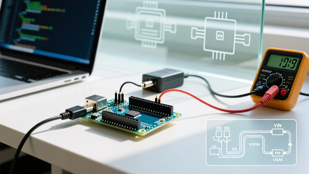
- Check the ON LED: If it is dim or flickering, you are experiencing a brownout. Measure the 5V pin with a multimeter under load.
- Feel the Regulator: If the NCP1117 is too hot to touch (>60°C), you are exceeding its thermal budget. Lower the VIN voltage or reduce the load.
- Inspect the Polyfuse: If the board works on a wall adapter but not via USB, the PTC fuse may be permanently degraded from repeated over-current tripping.
- Measure Ground Continuity: Ensure all external modules share a common ground with the Arduino. Floating grounds cause erratic ADC readings and logic failures.
Mastering these power configurations ensures your microcontroller projects remain stable, efficient, and safe from catastrophic electrical failure.