
The Case for Upgrading Your Arduino Mic Setup
For years, the standard approach to capturing audio in the maker community relied on analog electret microphone modules. If you have been building voice-activated relays, basic frequency analyzers, or simple audio recorders, you are likely familiar with the MAX9814 amplifier board or the ubiquitous KY-038 sound sensor. However, as edge AI, offline voice recognition, and high-fidelity audio streaming become standard in 2026, the limitations of analog audio on 8-bit microcontrollers have become a severe bottleneck.
Migrating your Arduino mic setup from analog to digital MEMS (Micro-Electro-Mechanical Systems) is no longer just an optional audiophile upgrade; it is a necessity for modern MCU projects. Digital interfaces like I2S (Inter-IC Sound) and PDM (Pulse Density Modulation) bypass the microcontroller's internal ADC entirely, eliminating analog ground noise, quantization errors, and sampling rate limitations.
The Analog Bottleneck: Why Legacy Modules Fail
Legacy analog modules output a biased voltage (typically a 1.25V DC offset with an AC audio signal riding on top). When fed into an ATmega328P's 10-bit ADC via analogRead(), you face three critical failure modes:
- Sampling Rate Limits: The standard Arduino Uno struggles to exceed a 9.6kHz practical sampling rate when using
analogRead()in a loop, resulting in aliasing and poor voice clarity. - Quantization Noise: A 10-bit ADC yields only 1,024 discrete steps. Quiet sounds are lost in the noise floor, while loud sounds clip aggressively.
- Useless Comparators: The ultra-cheap KY-038 modules use an LM393 comparator. They do not output audio; they output a simple HIGH/LOW digital trigger based on a potentiometer threshold. They are entirely useless for actual audio processing.
Technology Comparison: Legacy Analog vs. Modern Digital MEMS
When planning your migration, it is vital to select the right digital protocol for your target microcontroller. Below is a comparison of the most common microphone modules available in the 2026 market.
| Module / IC | Interface | Resolution | SNR | Est. Cost (2026) | Best Use Case |
|---|---|---|---|---|---|
| MAX9814 (Electret) | Analog (ADC) | 10-bit (MCU limited) | ~60 dB | $12.00 | Legacy AVR projects |
| KY-038 (LM393) | Digital Trigger | 1-bit (Threshold) | N/A | $1.50 | Clap switches / Noise triggers |
| INMP441 (MEMS) | I2S | 24-bit | 61 dB | $2.50 | Hi-Fi ESP32 / RP2040 Audio |
| SPH0645LM4H (MEMS) | I2S | 24-bit (18-bit valid) | 65 dB | $2.20 | Budget I2S voice capture |
| MP34DT061 (MEMS) | PDM | 1-bit (High Rate) | 66 dB | $3.50 | Arduino Nano 33 BLE Sense |
Hardware Migration: Wiring the I2S MEMS Microphone
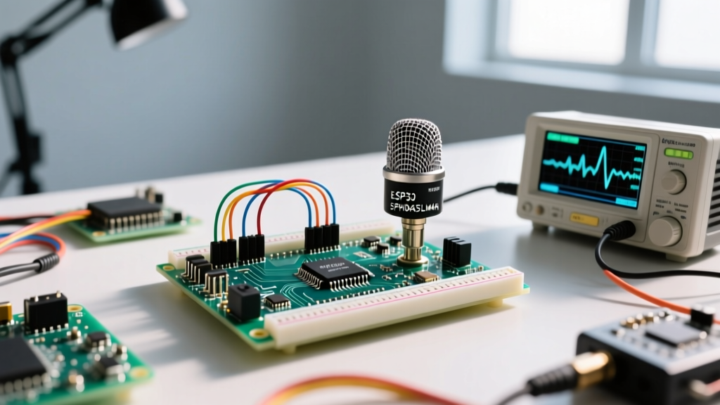
Because standard 8-bit AVR chips (like the ATmega328P) lack hardware I2S peripherals, migrating to an I2S Arduino mic usually requires upgrading your microcontroller to a 32-bit architecture. The ESP32-S3 and Raspberry Pi RP2040 are the current standards for audio-capable maker boards, featuring dedicated I2S hardware and DMA (Direct Memory Access) controllers.
INMP441 to ESP32-S3 Pinout Mapping
The INMP441 is an omnidirectional MEMS microphone with a bottom port, offering excellent flat frequency response from 100Hz to 10kHz. Here is the exact wiring matrix for migrating to an ESP32-S3:
- VDD: Connect to 3.3V (Do NOT use 5V; the internal LDO will overheat and introduce thermal noise).
- GND: Connect to MCU GND.
- SD (Serial Data): Connect to GPIO 14 (I2S Data In).
- WS (Word Select): Connect to GPIO 15 (I2S LRCLK).
- SCK (Clock): Connect to GPIO 16 (I2S BCLK).
- L/R (Channel Select): Connect to GND to output on the Left channel, or VDD for the Right channel.
Critical Edge Case: Never leave the L/R pin on the INMP441 floating. If left unconnected, the microphone's internal multiplexer will randomly switch channels or output zeroed frames, resulting in severe audio dropouts that mimic hardware failure. Always tie it to a defined logic level.
Software Migration: Ditching analogRead() for DMA Buffers
The most significant shift when upgrading your Arduino mic is moving from polling-based analog reads to interrupt-driven DMA buffers. With I2S, the microcontroller's I2S peripheral handles the high-speed clocking and data shifting, writing the 32-bit audio samples directly into SRAM without CPU intervention.
According to the Espressif I2S API Reference, configuring the DMA buffer size is critical. A buffer that is too small (e.g., 64 frames) will cause buffer underruns and audio popping if your main loop experiences WiFi or Bluetooth interrupts. For stable 44.1kHz audio capture, configure your DMA buffer to hold at least 512 frames, utilizing dual-buffering (ping-pong buffers) to ensure continuous data flow while the CPU processes the inactive buffer.
The PDM Alternative for Official Arduino Boards
If your project mandates the use of an official Arduino board rather than an ESP32, the migration path shifts to PDM (Pulse Density Modulation). Boards like the Arduino Nano 33 BLE Sense feature onboard PDM microphones and specialized hardware accelerators. The Arduino Official PDM Microphone Guide details how to use the PDM.h library to capture audio and feed it directly into the board's CMSIS-DSP library for real-time FFT analysis or TinyML voice keyword spotting.
Real-World Troubleshooting & Failure Modes
When migrating from analog to digital, engineers frequently encounter specific silicon-level bugs and timing issues that are rarely documented in basic tutorials.
1. The SPH0645LM4H LSB Timing Bug
The Knowles SPH0645LM4H is a highly popular, budget-friendly I2S mic. However, it features a well-documented silicon erratum regarding I2S timing. The microphone shifts its data out one clock cycle later than the I2S standard dictates. If you read the raw 32-bit integer from the DMA buffer, the audio will sound like harsh, distorted static.
The Fix: You must manually bit-shift the incoming sample to the right by one position (sample = sample >> 1;) and mask the sign bit if your MCU does not automatically handle the 24-bit to 32-bit sign extension. Alternatively, some modern ESP32 I2S drivers allow you to invert the BCLK edge in software to compensate for the timing shift.
2. High-Frequency Hiss and Ground Loops
MEMS microphones are incredibly sensitive to power supply ripple. If you are powering your ESP32 via a cheap USB switching regulator, the 500kHz switching noise will couple into the I2S data lines, manifesting as a high-frequency hiss in your audio spectrum.
The Fix: Place a 100nF ceramic decoupling capacitor as close to the VDD and GND pins of the MEMS microphone breakout board as possible. Furthermore, ensure that the ground path between the MCU and the microphone is thick and direct; avoid daisy-chaining grounds through high-current peripherals like motor drivers or LED strips.
3. Clipping on Loud Transients
While MEMS mics offer high dynamic range, the acoustic overload point (AOP) of the INMP441 is 116 dB SPL. If you are recording in loud environments (e.g., near machinery or live music), the acoustic membrane itself will clip before the digital interface maxes out. For high-SPL environments, consider migrating to the TDK INMP441 alternatives specifically rated for 120+ dB SPL, or implement a physical acoustic mesh to attenuate wind and pressure spikes.
Summary
Upgrading your Arduino mic from legacy analog modules to I2S or PDM digital MEMS sensors is a transformative step for any embedded audio project. By bypassing the ADC, utilizing DMA buffers, and selecting the appropriate 32-bit microcontroller, you unlock studio-quality audio capture, pristine signal-to-noise ratios, and the ability to run advanced edge-AI voice models directly on the microcontroller.