
The Paradigm Shift: From Abstraction to Bare Metal
When beginners first arduino learn the ropes, they typically rely on high-level abstractions. Functions like digitalWrite() and analogRead() are designed to lower the barrier to entry, allowing makers to blink LEDs and read sensors within minutes. However, as projects scale in complexity—integrating real-time motor control, low-power sleep modes, or high-speed data acquisition—these abstractions become bottlenecks. To transition from a hobbyist to an embedded systems engineer in 2026, you must understand the silicon executing your C++ code.
The Maker's Reality Check: The Arduino IDE hides the hardware registers. To debug complex timing issues, eliminate jitter, or prevent memory crashes, you must understand what the microcontroller is actually doing at the clock-cycle level when you call standard library functions.
Decoding the Silicon: Core MCU Architectures
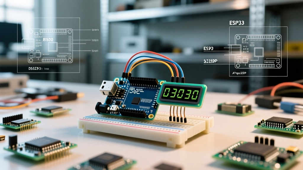
The landscape of beginner microcontrollers has shifted significantly. While the classic Arduino Uno R3 (based on the 8-bit ATmega328P) remains a staple in legacy tutorials, the Arduino Official Getting Started Guide now heavily features the Uno R4 series. The R4 Minima and R4 WiFi utilize the Renesas RA4M1, a 32-bit ARM Cortex-M4 processor, fundamentally changing the mathematical and architectural rules of your sketches.
| Feature | Uno R3 (Classic AVR) | Uno R4 Minima (Modern ARM) |
|---|---|---|
| Core Architecture | 8-bit ATmega328P | 32-bit ARM Cortex-M4 (Renesas RA4M1) |
| Clock Speed | 16 MHz | 48 MHz |
| ADC Resolution | 10-bit (1024 levels) | 14-bit (16384 levels, 12-bit default) |
| DAC (Digital to Analog) | None (Requires external PWM filtering) | 12-bit True Analog Output (1 channel) |
| Typical 2026 Price | ~$27.50 | ~$27.50 |
The Four Pillars of Hardware Interaction
To truly master microcontroller programming, you must move beyond copying sketches and understand the four primary hardware interfaces.
1. GPIO: Sourcing, Sinking, and the 20mA Limit
General Purpose Input/Output (GPIO) pins are not infinite power sources. According to the Microchip ATmega328P Datasheet, the absolute maximum current per I/O pin is 40mA, but the recommended continuous operating limit is 20mA. Exceeding this causes voltage drops, thermal throttling, and permanent silicon degradation.
- Sourcing vs. Sinking: Microcontrollers are often better at sinking current (connecting the load to VCC and pulling the pin LOW) than sourcing current (pin HIGH to GND). This is due to the lower resistance of the internal NMOS transistors compared to the PMOS transistors in the push-pull output stage.
- Internal Pull-ups: Using
pinMode(pin, INPUT_PULLUP)engages an internal 20kΩ to 50kΩ resistor. This is excellent for debouncing mechanical switches without external components, but it is entirely unsuitable for high-speed I2C bus pull-ups, which require precise 4.7kΩ external resistors to maintain sharp signal edges. - Inductive Kickback: Never drive a relay coil or solenoid directly from a GPIO pin. The collapsing magnetic field generates a reverse voltage spike that will instantly destroy the MCU's output transistor. Always use a logic-level MOSFET (like the IRLZ44N) and a flyback diode (1N4007).
2. ADC: Resolution, VREF, and the Nyquist Theorem
Analog-to-Digital Conversion (ADC) translates real-world voltages into discrete digital integers. As detailed in SparkFun's Analog-to-Digital Conversion Tutorial, the resolution dictates the smallest voltage change the MCU can detect.
On a 5V Uno R3 with a 10-bit ADC, each step represents 4.88mV (5V / 1024). On the 3.3V Uno R4 with a 14-bit ADC, each step represents a highly precise 0.2mV. However, resolution is useless without proper sampling techniques:
- Source Impedance: The ADC uses an internal sample-and-hold capacitor. If your sensor's output impedance is too high (typically >10kΩ), the capacitor won't charge fully during the sampling window, resulting in artificially low readings. Use an op-amp voltage follower for high-impedance sources like piezo sensors.
- Voltage Reference (VREF): By default, the ADC uses the board's VCC as the reference. If your USB power dips from 5.0V to 4.7V, your sensor readings will drift wildly. Use
analogReference(INTERNAL)to switch to the MCU's stable internal bandgap reference (1.1V on AVR, 1.45V/2.5V on RA4M1) for precision measurements. - Nyquist-Shannon Theorem: To accurately reconstruct an AC signal, you must sample at least twice its highest frequency. The ATmega328P ADC takes ~104 microseconds per conversion (approx. 9.6kHz max sample rate), making it incapable of accurately sampling standard 20kHz audio signals without severe aliasing.
3. PWM: Timer Registers vs. analogWrite()
The analogWrite() function is a misnomer; it does not output analog voltage. It outputs Pulse Width Modulation (PWM)—a digital square wave toggling between 0V and 5V at a high frequency. The "analog" effect is achieved by varying the duty cycle (the percentage of time the pin is HIGH).
Critical edge cases arise when modifying PWM frequencies. On the ATmega328P, Pins 5 and 6 are tied to Timer0. Timer0 is also responsible for the millis(), micros(), and delay() functions. If you alter the Timer0 prescaler to change the PWM frequency (e.g., to push it above the 20kHz human hearing threshold for silent motor control), you will completely break your sketch's timekeeping functions. Always use Timer1 (Pins 9 and 10) or Timer2 (Pins 11 and 3) for custom frequency PWM generation.
Memory Mapping: Where Your Code Actually Lives
Out-of-memory crashes are the most common point of failure for intermediate makers. Unlike your PC, an MCU has strictly partitioned Harvard architecture memory. Understanding these segments is non-negotiable:
- Flash Memory (Program Space): Where your compiled code and constant strings live. The ATmega328P has 32KB, while the RA4M1 boasts 256KB. Flash is non-volatile but has a limited write endurance (~10,000 cycles).
- SRAM (Static Random Access Memory): Where your variables, arrays, and the call stack reside during runtime. The ATmega328P has a meager 2KB. If your global variables and local function stacks exceed 2KB, the stack will collide with the heap, causing silent data corruption and random reboots.
- EEPROM / Data Flash: Non-volatile memory for storing user settings, calibration data, or device states that must survive power loss. The AVR offers 1KB of byte-addressable EEPROM, whereas the RA4M1 uses 8KB of Data Flash (which requires block-erase operations rather than simple byte writes).
Pro-Tip for SRAM Conservation: String literals like Serial.println("System Initialized"); are copied from Flash to SRAM at boot, wasting precious RAM. Always wrap static strings in the F() macro: Serial.println(F("System Initialized"));. This forces the MCU to read the string directly from Flash memory during execution, keeping your SRAM free for dynamic variables.
Strategic Learning Path for Advanced Makers
To move beyond basic tutorials and achieve true embedded literacy, follow this structured progression:
- Datasheet Literacy: Stop relying solely on forum posts. Download the official ATmega328P or RA4M1 datasheet and learn to read the "Electrical Characteristics" and "Register Description" tables.
- Bare-Metal Register Manipulation: Learn to bypass Arduino functions. Instead of
digitalWrite(13, HIGH), which takes ~50 clock cycles, learn to writePORTB |= (1 << PB5), which executes in a single clock cycle and eliminates timing jitter. - Hardware Interrupts (ISR): Move away from
polling(checking a pin state in theloop()). Learn to configure External Interrupts (INT0/INT1) and Pin Change Interrupts (PCINT) to wake the MCU or trigger an Instantaneous Service Routine (ISR) only when an event occurs. Remember to declare variables modified inside an ISR asvolatile. - Real-Time Operating Systems (RTOS): Once you transition to 32-bit ARM boards like the Uno R4 or ESP32, abandon the super-loop (
setup()andloop()) architecture. Implement FreeRTOS to manage concurrent tasks, semaphores, and priority-based scheduling.
Mastering these core concepts transforms the way you arduino learn and build. By respecting the physical limitations of the silicon and understanding the architectural decisions made by the microcontroller's designers, you will write faster, more reliable, and highly optimized firmware capable of handling the demanding IoT and robotics applications of 2026 and beyond.