
The Core Compatibility Matrix: Voltage and Current Limits
When makers first explore the intersection of Arduino and LED technologies, the assumption is often that any light-emitting diode can be wired directly to any microcontroller GPIO pin. In 2026, with the maker ecosystem heavily fragmented across 5V legacy boards, 3.3V ARM Cortex-M4 architectures, and dual-core IoT SoCs, this assumption is a fast track to silicon failure. True compatibility hinges on three strict electrical parameters: logic level voltage thresholds, per-pin current sourcing limits, and forward voltage ($V_f$) matching.
Before wiring a single anode, you must understand the physical limits of your microcontroller's output pins. Exceeding these limits causes immediate thermal shutdown or permanent degradation of the silicon die.
GPIO Current Sourcing: R3 vs. R4 vs. ESP32
- Arduino Uno R3 (ATmega328P): The classic 5V board features an absolute maximum rating of 40mA per GPIO pin, but the recommended continuous operating current is 20mA. The total VCC/GND aggregate limit is 200mA.
- Arduino Uno R4 Minima/WiFi (Renesas RA4M1): Modern 32-bit ARM boards operate at 5V but have much stricter silicon limits. The recommended maximum current per pin is just 8mA, with a total package limit that requires careful power budgeting across all active pins.
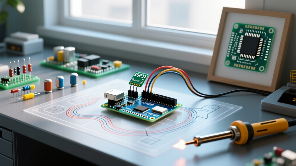
- ESP32-S3 (Native 3.3V): Widely used in the Arduino IDE environment, these boards output 3.3V logic. The absolute maximum source/sink current per pin is 40mA, but drawing more than 12mA per pin is highly discouraged to prevent voltage sag and brownout resets.
Standard 5mm Through-Hole LEDs: The Baseline
Standard 5mm through-hole LEDs remain the most common entry point for Arduino and LED projects. Compatibility here is dictated entirely by Ohm's Law and the specific chemistry of the LED die, which determines its forward voltage ($V_f$).
Forward Voltage and Resistor Mathematics
Different LED colors utilize different semiconductor materials, resulting in varying voltage drops. To interface these safely with a 5V Arduino Uno, you must calculate the correct current-limiting resistor.
| LED Color | Typical $V_f$ | Target Current | Required Resistor (at 5V) |
|---|---|---|---|
| Red (AlGaInP) | 1.8V - 2.2V | 15mA | 220Ω |
| Yellow/Green | 2.0V - 2.4V | 15mA | 220Ω |
| Blue/White (InGaN) | 3.0V - 3.4V | 15mA | 100Ω to 150Ω |
Calculation Formula: $R = (V_{source} - V_f) / I_{target}$. For a Red LED on a 5V pin: $(5V - 2.0V) / 0.015A = 200Ω$. The nearest standard E12 resistor value is 220Ω.
2026 Best Practice: Always use 1/4W (0.25W) metal film resistors with a 1% tolerance for consistent brightness across LED arrays. Carbon composition resistors introduce unnecessary thermal noise and drift.
Addressable RGB LEDs: The 3.3V vs 5V Logic Trap
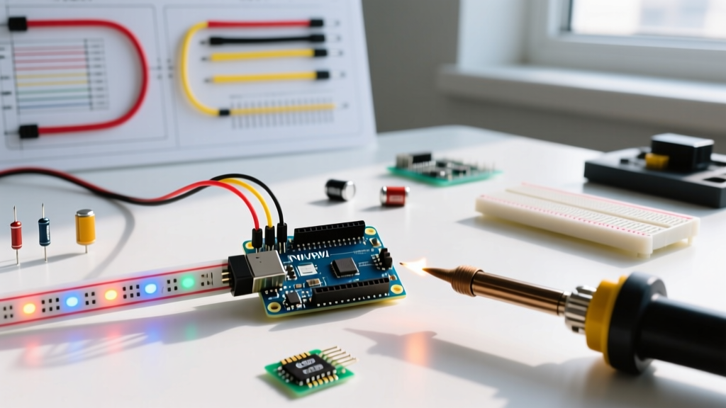
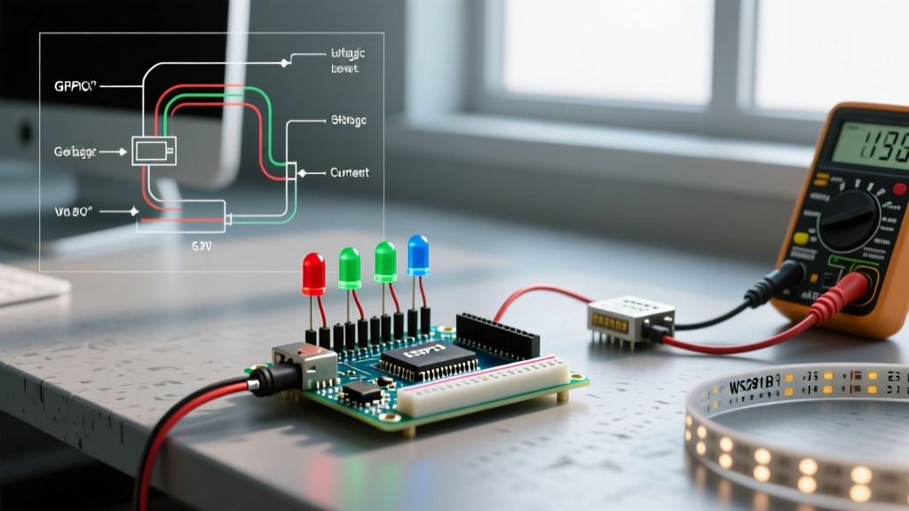
The WS2812B (NeoPixel) and SK6812 addressable LED ecosystems dominate modern lighting projects. However, integrating these with modern 3.3V microcontrollers (like the ESP32 or Arduino Nano 33 IoT) introduces a severe logic-level incompatibility that plagues thousands of projects.
The Data Line Voltage Threshold ($V_{IH}$)
According to the WS2812B datasheet, the LED expects a 5V power supply ($V_{DD}$). Consequently, the minimum voltage required on the DIN (Data In) pin to register a logical 'HIGH' ($V_{IH}$) is $0.7 imes V_{DD}$, which equals 3.5V.
If you connect an ESP32 (which outputs a maximum of 3.3V on its GPIO pins) directly to the WS2812B data line, the 3.3V signal falls short of the 3.5V threshold. This results in the classic failure mode: flickering, random color bursts, or the first LED in the chain working while the rest remain dead.
The Level Shifter Solution: To bridge this gap, you must use a dedicated logic level translator. The SN74AHCT125 (available for roughly $0.65 in DIP or SOIC packages) is the gold standard. It accepts 3.3V logic on the input and, when powered by 5V, outputs a rock-solid 5V logic signal to the LED data line. As detailed in the comprehensive Adafruit NeoPixel UberGuide, bypassing this level shifter on 3.3V boards is the leading cause of addressable LED instability.For deeper architectural insights on bridging voltage domains safely, Texas Instruments provides extensive documentation on logic level translation topologies that apply directly to high-speed LED data protocols.
High-Power LEDs (1W - 3W): Why Direct GPIO Connection Fails
High-power illumination LEDs, such as the Cree XP-E2 or Luxeon Rebel series, draw between 350mA and 1000mA at forward voltages ranging from 2.8V to 3.6V. No Arduino or ESP32 GPIO pin can supply this current. Attempting to do so will instantly vaporize the microcontroller's internal trace.
Constant Current Drivers vs. Logic-Level MOSFETs
When designing the driver stage for high-power Arduino and LED setups, you have two primary paths:
- Logic-Level N-Channel MOSFET (PWM Dimming): Using a component like the IRLZ44N (costing ~$1.20). The critical parameter here is the Gate-Source Threshold Voltage ($V_{gs(th)}$). You must select a MOSFET with a $V_{gs(th)}$ well below your microcontroller's logic level (e.g., < 2.5V for 3.3V boards) to ensure the MOSFET fully saturates and minimizes $R_{DS(on)}$ heat generation. Note: MOSFETs do not regulate current; you must rely on the LED's internal thermal rollover or add a series resistor, which is highly inefficient.
- Constant Current Buck Driver (Recommended): Using a dedicated driver like the Mean Well LDD-300L (~$4.80). This component steps down the voltage and strictly regulates the current to 300mA regardless of LED temperature fluctuations. The Arduino simply sends a 5V PWM signal to the driver's DIM pin to control brightness with 10-bit or 12-bit resolution.
PWM Frequency Compatibility for LED Dimming
Pulse Width Modulation (PWM) is how microcontrollers simulate analog dimming for LEDs. However, default PWM frequencies can cause unexpected compatibility issues.
- Arduino Uno R3: Default PWM frequency is approximately 490Hz (pins 5 and 6 are 980Hz). This is generally acceptable for visual dimming but can cause visible flickering if recorded on high-framerate cameras.
- ESP32 (LEDC Peripheral): Allows software-defined PWM frequencies up to 5kHz or higher. When driving high-power LEDs through a MOSFET, operating at 490Hz can sometimes induce an audible high-pitched whine due to piezoelectric effects in the circuit or gate capacitance. Bumping the ESP32 LEDC frequency to 2kHz - 4kHz eliminates this acoustic noise while maintaining smooth dimming.
Board-to-LED Compatibility Matrix
Use this quick-reference matrix to determine the necessary interface components for your specific Arduino and LED combination.
| Microcontroller Board | Logic Level | Standard 5mm LED | WS2812B / SK6812 | 1W High-Power LED |
|---|---|---|---|---|
| Arduino Uno R3 | 5V | Direct + Resistor | Direct (5V Data) | MOSFET or LDD Driver |
| Arduino Uno R4 Minima | 5V | Direct + Resistor (Max 8mA) | Direct (5V Data) | MOSFET or LDD Driver |
| ESP32-S3 DevKit | 3.3V | Direct + Resistor | Requires SN74AHCT125 | Logic-Level MOSFET |
| Arduino Nano 33 IoT | 3.3V | Direct + Resistor | Requires SN74AHCT125 | Logic-Level MOSFET |
Frequently Asked Questions
Can I wire multiple standard LEDs in parallel to a single Arduino pin?
No. Wiring LEDs in parallel without individual resistors for each diode leads to current hogging. Because no two LEDs have the exact same $V_f$ due to manufacturing tolerances, the LED with the lowest $V_f$ will draw the majority of the current, overheat, and fail, subsequently cascading the failure to the remaining LEDs. Always wire them in parallel with individual resistors, or wire them in series if your supply voltage permits.
Why do my WS2812B LEDs show random colors when using an ESP32?
This is the classic 3.3V logic incompatibility. The ESP32 outputs 3.3V, but the WS2812B requires a minimum of 3.5V to register a logical HIGH on the data line. You must use a logic level shifter like the SN74AHCT125 powered by 5V to translate the ESP32's 3.3V data signal to a 5V signal. Additionally, ensure you are injecting 5V power into the LED strip every 50 pixels to prevent voltage sag.
Do I need a heatsink for my logic-level MOSFET when dimming a 1W LED?
If you are using a proper logic-level MOSFET like the IRLZ44N and driving it with a sufficient gate voltage (ensuring it is fully in the ohmic region), the $R_{DS(on)}$ is extremely low (typically ~22mΩ). At 350mA, the power dissipated as heat is $I^2 imes R = (0.35)^2 imes 0.022 = 0.0027W$. This is negligible, and a heatsink is entirely unnecessary for single 1W LEDs. However, if you are switching multiple 3W LEDs, thermal management becomes mandatory.
How do I verify Arduino hardware specs for current limits?
Always consult the official microcontroller datasheet rather than third-party summaries. For modern boards, the official Arduino hardware documentation provides the exact per-pin and aggregate current limits required to calculate safe resistor values and multiplexing matrices.