
Building a Precision Current Detector with Arduino
Accurately measuring electrical current is a foundational skill for any embedded systems engineer or DIY maker. Whether you are profiling the power consumption of a battery-operated IoT node, monitoring a solar charge controller, or implementing over-current protection for a motor driver, a reliable current detector is essential. While older Hall-effect sensors like the ACS712 were once the default choice, they suffer from high noise floors and poor resolution at low currents. In 2026, the industry standard for DC current detection in maker projects has decisively shifted to shunt-based I2C monitors, specifically the Texas Instruments INA219.
This comprehensive tutorial will walk you through designing, wiring, and programming a high-precision current detector Arduino setup using the INA219 breakout board. We will cover the underlying mathematics of shunt calibration, hardware integration with modern microcontrollers like the Arduino Uno R4, and real-world troubleshooting for I2C communication failures.
Sensor Selection: Why the INA219 Dominates in 2026
Before diving into the wiring, it is critical to understand why we are choosing the INA219 over alternatives. The table below compares the three most common current sensing modules available on the market today.
| Feature | INA219 (Shunt/I2C) | ACS712 (Hall-Effect) | SCT-013 (Split-Core CT) |
|---|---|---|---|
| Measurement Type | DC Current & Voltage | AC / DC Current | AC Current Only |
| Interface | I2C (Digital) | Analog Voltage | Analog Voltage (3.5mm jack) |
| Resolution | 12-bit ADC (High) | 10-bit (Limited by MCU ADC) | Depends on MCU ADC |
| Typical 2026 Price | $4.50 - $6.00 | $2.50 - $3.50 | $11.00 - $15.00 |
| Best Use Case | Precision DC power profiling | High-current AC/DC motor control | Non-invasive AC mains monitoring |
For DC applications, the Texas Instruments INA219 datasheet reveals a built-in programmable gain amplifier (PGA) and a 12-bit ADC. This allows the chip to measure shunt voltages as low as 10µV, translating to milliamp-level resolution that an Arduino's native 10-bit analog-to-digital converter simply cannot achieve via the ACS712.
Hardware Bill of Materials (BOM)
- Microcontroller: Arduino Uno R4 Minima or Nano ESP32 (Approx. $22.00 - $27.50)
- Sensor: INA219 Breakout Board (Adafruit or generic equivalent, Approx. $5.50)
- Passives: 100nF (0.1µF) MLCC decoupling capacitors, 4.7kΩ pull-up resistors (if not pre-populated on breakout)
- Wiring: 22 AWG silicone stranded wire for power paths, 26 AWG for I2C data lines
- Load: A DC load to measure (e.g., a 12V DC water pump or LED strip)
Step-by-Step Wiring Guide
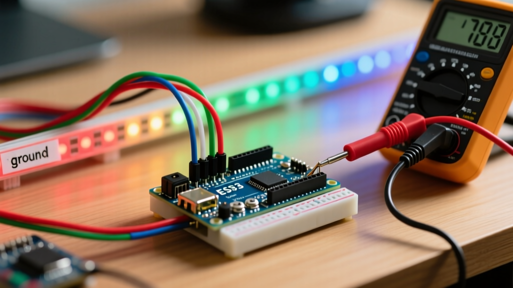
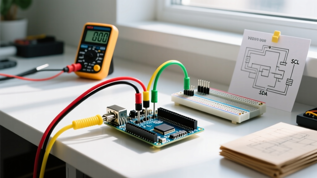
The INA219 communicates via I2C, requiring only four connections to the microcontroller. However, the load wiring must be handled carefully to avoid ground loops and voltage drops.
1. I2C Data and Power Connections
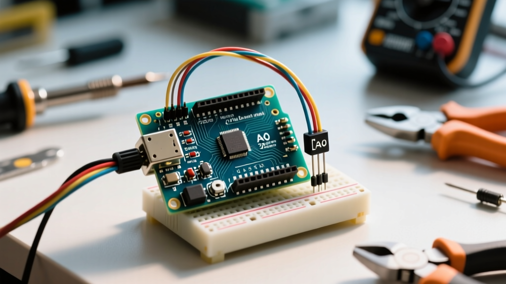
- Connect the breakout VCC pin to the Arduino 5V (or 3.3V if using a Nano ESP32).
- Connect GND to the Arduino GND.
- Connect SCL to the Arduino I2C clock pin (A5 on Uno R3, dedicated SCL header on Uno R4).
- Connect SDA to the Arduino I2C data pin (A4 on Uno R3, dedicated SDA header on Uno R4).
2. Load Path Wiring (High-Side Sensing)
The INA219 is designed for high-side current sensing. This means it sits between the positive power supply and the load.
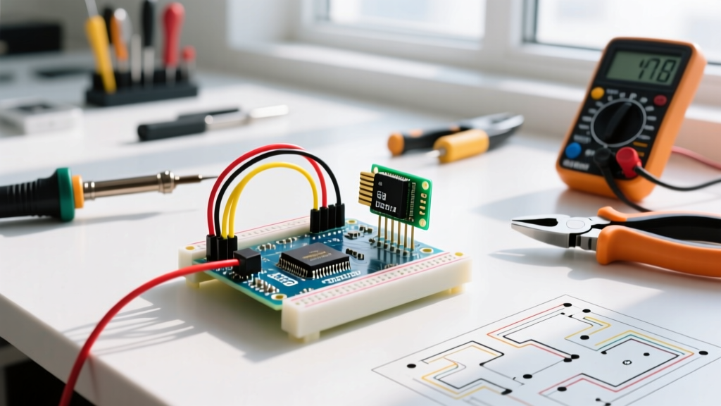
- Connect your power supply positive terminal to the INA219 VIN+ screw terminal.
- Connect the INA219 VIN- screw terminal to the positive input of your load.
- Connect the power supply negative (Ground) directly to the negative input of your load.
⚠️ Critical Warning: Never connect the load ground to the INA219 VIN- terminal. The sensor only measures the voltage drop across the internal shunt resistor on the high side. Sharing a ground reference through the sensor's load path will bypass the shunt and result in zero current readings, or worse, damage the internal ESD protection diodes.
Programming the Current Detector Arduino Sketch
To interface with the sensor, we utilize the Arduino Wire library alongside Adafruit's robust INA219 abstraction layer. You can install the Adafruit INA219 library via the Arduino Library Manager.
Below is the optimized C++ sketch for polling the sensor at a 10Hz interval, calculating real-time power dissipation, and outputting the data over the serial monitor.
#include <Wire.h>
#include <Adafruit_INA219.h>

Adafruit_INA219 ina219;

void setup(void) {
  Serial.begin(115200);
  while (!Serial) delay(10);

  Serial.println("Initializing INA219 Current Detector...");

  // Initialize with default I2C address 0x40
  if (!ina219.begin()) {
    Serial.println("Failed to find INA219 chip. Check I2C wiring.");
    while (1) { delay(10); }
  }

  // Calibrate for higher current resolution (up to 3.2A)
  // Default is 32V and 2A. This changes PGA gain to /8.
  ina219.setCalibration_32V_2A();
  Serial.println("INA219 Initialized Successfully.");
}

void loop(void) {
  float shuntvoltage = ina219.getShuntVoltage_mV();
  float busvoltage = ina219.getBusVoltage_V();
  float current_mA = ina219.getCurrent_mA();
  float power_mW = ina219.getPower_mW();
  float loadvoltage = busvoltage + (shuntvoltage / 1000);

  Serial.print("Bus: "); Serial.print(busvoltage); Serial.print(" V | ");
  Serial.print("Shunt: "); Serial.print(shuntvoltage); Serial.print(" mV | ");
  Serial.print("Current: "); Serial.print(current_mA); Serial.print(" mA | ");
  Serial.print("Power: "); Serial.print(power_mW); Serial.println(" mW");

  delay(100); // 10Hz polling rate
}
Deep Dive: Calibration and Shunt Mathematics
Understanding the math behind the setCalibration_32V_2A() function is what separates novices from experts. The INA219 breakout boards typically ship with a 0.1Ω (100mΩ) surface-mount shunt resistor.
According to Ohm's Law (V = I × R), if the maximum expected current is 2.0A, the voltage drop across the shunt will be:
V_shunt = 2.0A × 0.1Ω = 0.2V (200mV)
The INA219's internal ADC measures this shunt voltage. However, the chip features a Programmable Gain Amplifier (PGA). If you attempt to measure currents exceeding 3.2A with a 0.1Ω shunt, the shunt voltage will exceed 320mV, saturating the ADC and triggering an over-flow bit in the calibration register. If your project requires measuring up to 5A, you must physically desolder the 0.1Ω resistor and replace it with a 0.05Ω (50mΩ) shunt, then recalculate the calibration register in software using the formula provided in the Adafruit INA219 calibration guide.
Real-World Troubleshooting and Failure Modes
When deploying a current detector Arduino circuit in the field, you will inevitably encounter edge cases. Here is how to diagnose the most common hardware and software failures:
1. I2C Bus Lockups and Noise
Symptom: The Arduino freezes, or the serial monitor outputs NaN or 0.00 for all values after a motor starts.
Cause: Inductive kickback from motors or long I2C wire runs acting as antennas, introducing electromagnetic interference (EMI) that corrupts the I2C clock line.
Solution:
- Add 4.7kΩ pull-up resistors to both SDA and SCL lines if your breakout board lacks them.
- Place a 100nF ceramic decoupling capacitor directly across the VCC and GND pins of the INA219 breakout.
- Keep I2C traces under 30cm in length. For longer runs, use an I2C bus extender like the PCA9615.
2. Negative Current Readings
Symptom: The serial monitor displays negative milliamp values when the load is actively consuming power.
Cause: The sensor is wired in reverse. Current is flowing from VIN- to VIN+ instead of VIN+ to VIN-.
Solution: Swap the physical wires at the screw terminals. Alternatively, you can invert the value in software by multiplying current_mA by -1, but fixing the hardware topology is the recommended engineering practice.
3. Bus Voltage Reads 0.00V but Current is Accurate
Symptom: Shunt voltage and current calculate correctly, but Bus Voltage returns zero.
Cause: The common-mode voltage limit has been exceeded, or the GND reference of the INA219 is not shared with the load's ground reference.
Solution: Ensure the Arduino GND, INA219 GND, and Power Supply GND are all tied to a single common star-ground point. The INA219 can only measure bus voltages up to 26V safely; exceeding 26V will permanently destroy the internal ADC front-end.
Summary
Building a reliable current detector with an Arduino using the INA219 provides laboratory-grade power profiling capabilities at a fraction of the cost of commercial bench equipment. By respecting the high-side wiring topology, understanding the PGA shunt mathematics, and implementing proper I2C noise mitigation, your embedded projects will benefit from highly accurate, real-time telemetry data essential for advanced battery management and fault detection systems.