
The Ultimate Quick-Reference Guide for Arduino RC Cars
Building a custom Arduino radio control car bridges the gap between basic microcontroller blinking and real-world robotics. However, moving from a breadboard to a high-speed drivetrain introduces severe electrical noise, voltage sag, and signal latency. This FAQ and quick-reference guide skips the basic 'blink' tutorials and dives straight into the edge cases, hardware selection, and power management strategies required to build a reliable RC vehicle in 2026.
Motor Driver Selection Matrix
Choosing the right motor driver dictates your car's efficiency, heat dissipation, and top speed. Below is a quick-reference comparison of the three most common drivers used in DIY Arduino RC platforms.
| Driver IC | Topology | Continuous Current | Voltage Drop | Typical Cost | Best Use Case |
|---|---|---|---|---|---|
| L298N | BJT (Darlington) | 2.0A per channel | ~1.4V to 2.0V | $2.50 - $4.00 | High-current, low-speed heavy rovers where efficiency is secondary. |
| TB6612FNG | MOSFET | 1.2A per channel | ~0.5V | $3.50 - $5.00 | Standard 2WD/4WD RC cars requiring high PWM frequencies and low heat. |
| DRV8833 | MOSFET | 1.5A per channel | ~0.2V | $2.00 - $3.00 | Compact micro-rovers running on low-voltage (3.7V - 6V) single-cell LiPos. |
Expert Insight: The L298N is largely considered legacy hardware for high-speed RC cars. The internal Darlington transistor pairs waste massive amounts of power as heat. If you are running a 7.4V LiPo and your motors are rated for 6V, the L298N's 1.5V drop might seem convenient, but it will severely limit your run time. Upgrade to the TB6612FNG MOSFET driver for vastly superior thermal performance and logic-level switching.
Radio Frequency & Signal Integrity FAQs
Which RF module offers the best range-to-latency ratio for RC cars?
For an Arduino radio control car, latency is just as critical as range. A 100-millisecond delay at 20 mph means your car travels nearly 3 feet before it even begins to brake.
- nRF24L01+ (with PA/LNA): The gold standard for DIY RC. Operating at 2.4GHz via SPI, it offers sub-2ms latency and up to 1,000 meters of line-of-sight range when equipped with the Power Amplifier/Low Noise Amplifier (PA/LNA) antenna module. Cost: ~$4.50.
- HC-12 (433MHz): Uses UART and is incredibly easy to wire, but it suffers from 20ms to 50ms latency due to its internal buffering and lower baud rate constraints. Better for telemetry than real-time steering.
- ESP-NOW (ESP32-based): If you are upgrading from an 8-bit AVR to an ESP32, ESP-NOW over 2.4GHz Wi-Fi offers peer-to-peer latency under 5ms without needing a router, plus built-in telemetry channels.
Why does my nRF24L01+ drop connection the moment the motors spin up?
This is the most common failure mode in Arduino RC builds. It is caused by two distinct issues:
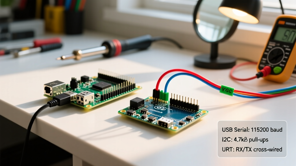
- Voltage Brownout: The nRF24L01+ draws spikes of up to 130mA during transmission. If your Arduino's 5V rail sags below 3.3V (or the module's internal LDO fails to regulate), the radio resets. Fix: Solder a 47µF to 100µF electrolytic capacitor directly across the VCC and GND pins of the nRF24L01+ breakout board.
- EMI / Back-EMF Noise: Brushed DC motors generate massive electromagnetic interference. Fix: Solder 0.1µF ceramic capacitors across the terminals of each DC motor, and from each terminal to the motor's metal casing. Keep the SPI wires (MOSI, MISO, SCK) under 10cm in length and route them away from the motor power cables.
Power Management & Battery FAQs
Can I power the Arduino Nano and the motors from the same LiPo battery?
Yes, but never wire the motors directly to the Arduino's onboard 5V pin or its VIN pin if you are using high-torque servos or drawing more than 100mA. The onboard linear regulator (typically an AMS1117-5.0) will overheat and trigger thermal shutdown, causing your car to drive away uncontrollably while the brain reboots.
The Correct Power Topology:
- Battery: 2S LiPo (7.4V nominal, 8.4V fully charged).
- Motor Driver VMOT: Connect directly to the LiPo positive terminal (via a main toggle switch and fuse).
- Logic Power: Use an LM2596 Buck Converter. Wire the LiPo to the buck converter's input, and use a multimeter to adjust the potentiometer until the output reads exactly 5.0V. Connect this 5V output to the Arduino Nano's
5Vpin (bypassing the onboard regulator entirely) and the nRF24L01+ VCC.
How do I monitor LiPo voltage without frying the Arduino's analog pin?
A fully charged 2S LiPo outputs 8.4V. Feeding this directly into the Arduino's A0 pin will destroy the microcontroller, which maxes out at 5V (or 3.3V on 3.3V boards). You must use a voltage divider. Referencing the principles of voltage divider circuits, use a 100kΩ resistor (R1) and a 47kΩ resistor (R2).
Calculation: Vout = Vin * (R2 / (R1 + R2))
Vout = 8.4V * (47,000 / 147,000) = 2.68V.
This safely keeps the analog read voltage well under the 5V limit while providing enough resolution to calculate the remaining battery percentage in your code.
Motor Control & Drivetrain FAQs
Why do my motors whine loudly, and how do I fix PWM frequencies?
The standard Arduino analogWrite() function generates a Pulse Width Modulation (PWM) signal at roughly 490Hz on most pins (and 980Hz on pins 5 and 6). This frequency falls squarely in the middle of the human hearing range, causing the motor coils to vibrate audibly.
The Fix: You can alter the hardware timers to push the PWM frequency into the ultrasonic range (above 20kHz), rendering it completely silent. For an Arduino Uno/Nano using the ATmega328P, you can modify Timer1 (which controls pins 9 and 10) by adding this line to your setup() function:
TCCR1B = TCCR1B & B11111000 | B00000001; // Sets Timer1 to 31,250 Hz
Warning: Changing timer frequencies will break the delay() and millis() functions if they rely on that specific timer. Plan your pin assignments accordingly, using Timer1 for motors and leaving Timer0 untouched for system timing.
My RC car struggles to turn at low speeds. How do I fix the deadzone?
DC motors require a minimum voltage to overcome static friction and cogging torque. If your code maps a joystick's 0-1023 analog read directly to a 0-255 PWM output, the first 20% of your joystick travel will do nothing.
Solution: Implement a software deadzone and minimum throttle mapping. Instead of map(val, 0, 1023, 0, 255), use a conditional function that snaps the output to the motor's minimum start voltage (usually around 60-80 out of 255) the moment the joystick leaves the physical center deadzone. This provides immediate, proportional low-speed crawling control.
Summary Checklist for First Power-On
- [ ] Buck converter tuned to 5.0V before connecting to the Arduino.
- [ ] 47µF capacitor soldered to the nRF24L01+ power rails.
- [ ] Motor logic pins (IN1, IN2) wired to PWM-capable Arduino pins.
- [ ] Common ground established between the LiPo, Buck Converter, Motor Driver, and Arduino.
- [ ] Wheels elevated off the ground during initial transmitter pairing and throttle testing.