
The Reality of Hobbyist Fire Detection
Building a flame detector Arduino project is a classic rite of passage for electronics enthusiasts. However, most online tutorials stop at a basic analogRead() function and an LED blink, ignoring the physical realities of infrared (IR) light. In real-world deployments, naive IR flame sensors trigger false alarms from sunlight, incandescent bulbs, and even heavy AC mains noise. According to the National Fire Protection Association (NFPA), reliable early detection is the cornerstone of fire safety, and while hobbyist sensors are not a replacement for UL-listed commercial smoke alarms, understanding their limitations and calibrating them correctly is vital for functional maker projects.
In this comprehensive 2026 guide, we will build a robust flame detection system using the Arduino Uno R4 Minima and the ubiquitous KY-026 IR sensor. We will go beyond basic wiring to implement a software moving-average filter, establish hardware hysteresis, and explore the physics of spectral light detection to eliminate false positives.
The Physics of IR Flame Detection
To troubleshoot a flame sensor, you must understand what it actually sees. The KY-026 module utilizes a phototransistor or photodiode optimized for near-infrared wavelengths. Specifically, it detects light in the 760nm to 1100nm spectrum, with peak sensitivity typically around 940nm.
When hydrocarbon-based fuels (wood, propane, butane) combust, they emit a massive spike in IR radiation within this exact band. However, the KY-026 cannot distinguish between the IR emitted by a campfire and the IR emitted by a 60W incandescent lightbulb or the sun. This spectral overlap is the primary cause of false positives in amateur flame detector Arduino builds. Mitigating this requires a combination of physical shrouding and intelligent software filtering.
Bill of Materials (BOM) and Cost Breakdown
Below is the exact hardware list used for this tutorial, reflecting standard maker market pricing in 2026. We highly recommend the Uno R4 Minima over the legacy R3 due to its 14-bit ADC, which provides vastly superior analog resolution for flame intensity mapping.
| Component | Model / Specification | Est. Price (2026) | Notes |
|---|---|---|---|
| Microcontroller | Arduino Uno R4 Minima | $20.00 | 14-bit ADC for precise IR readings |
| Flame Sensor | KY-026 IR Sensor Module | $1.50 - $3.00 | Includes onboard LM393 comparator |
| Relay Module | 5V Single-Channel Optocoupler | $2.50 | For triggering external alarms/fans |
| Audible Alarm | 5V Active Piezo Buzzer | $1.00 | Continuous tone, no PWM required |
| Resistors | 10kΩ and 220Ω (1/4W) | $0.10 | Pull-up and LED current limiting |
Pinout and Wiring Guide
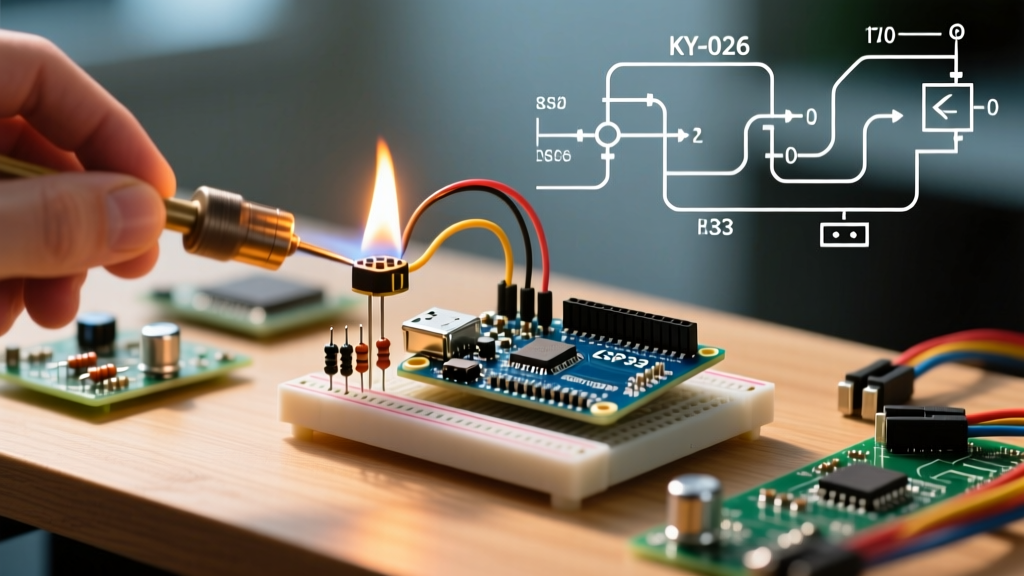
The KY-026 features four pins: VCC, GND, D0 (Digital), and A0 (Analog). While D0 provides a simple HIGH/LOW trigger based on an onboard potentiometer, relying solely on the digital pin limits your ability to map fire intensity or apply software debouncing. We will use both.
| KY-026 Pin | Arduino Uno R4 Pin | Function |
|---|---|---|
| VCC | 5V | Power supply (Do not use 3.3V) |
| GND | GND | Common ground reference |
| A0 | A0 | Analog IR intensity (0-1023 on 10-bit, up to 16383 on 14-bit) |
| D0 | D2 | Digital threshold trigger (Active LOW) |
Wiring Note: Connect the Relay Module IN pin to D8, and the Piezo Buzzer positive leg to D9. Ensure all grounds are tied together if using an external power supply for the relay.
Advanced C++ Code: Moving Average and Hysteresis
A common failure mode in basic flame detector Arduino sketches is relay chatter. When a flame flickers at the edge of the sensor's detection cone, the analog value oscillates rapidly around the threshold, causing the relay to click on and off dozens of times per second, eventually destroying the relay contacts.
To solve this, we implement a Moving Average Filter to smooth transient ADC noise, combined with Software Hysteresis to create distinct 'arm' and 'disarm' thresholds. For deeper understanding of analog signal processing on microcontrollers, refer to SparkFun's guide on Analog-to-Digital Conversion.
// Flame Detector Arduino with Moving Average & Hysteresis
const int analogPin = A0;
const int digitalPin = 2;
const int relayPin = 8;
const int buzzerPin = 9;

const int numReadings = 20; // Window size for moving average
int readings[numReadings];
int readIndex = 0;
long total = 0;
int average = 0;

// Thresholds for Hysteresis (Adjust based on 10-bit or 14-bit ADC)
// Lower values = closer/brighter flame on KY-026
const int FIRE_THRESHOLD = 300;
const int CLEAR_THRESHOLD = 450;

bool fireDetected = false;

void setup() {
  Serial.begin(115200);
  pinMode(digitalPin, INPUT);
  pinMode(relayPin, OUTPUT);
  pinMode(buzzerPin, OUTPUT);

  digitalWrite(relayPin, LOW);
  digitalWrite(buzzerPin, LOW);

  // Initialize array
  for (int i = 0; i < numReadings; i++) {
    readings[i] = 1023; // Default to 'no flame' (high resistance)
    total += readings[i];
  }
}

void loop() {
  // Subtract last reading
  total = total - readings[readIndex];
  // Read new analog value
  readings[readIndex] = analogRead(analogPin);
  // Add to total
  total = total + readings[readIndex];
  // Advance index
  readIndex = (readIndex + 1) % numReadings;
  // Calculate average
  average = total / numReadings;

  // Hysteresis Logic
  if (!fireDetected && average < FIRE_THRESHOLD) {
    fireDetected = true;
    triggerAlarm();
  }
  else if (fireDetected && average > CLEAR_THRESHOLD) {
    fireDetected = false;
    clearAlarm();
  }

  Serial.print("Raw: ");
  Serial.print(readings[readIndex]);
  Serial.print(" | Avg: ");
  Serial.println(average);

  delay(20); // Sample rate ~50Hz
}

void triggerAlarm() {
  digitalWrite(relayPin, HIGH);
  digitalWrite(buzzerPin, HIGH);
  Serial.println("!!! FIRE DETECTED !!!");
}

void clearAlarm() {
  digitalWrite(relayPin, LOW);
  digitalWrite(buzzerPin, LOW);
  Serial.println("Environment Clear.");
}
Calibration and Mitigating False Positives
Once the hardware is assembled and the code is uploaded, physical calibration is mandatory. The KY-026 features a blue 10kΩ trimpot (potentiometer) that sets the threshold for the D0 digital pin. While our code relies primarily on the A0 analog pin, setting the digital threshold correctly provides a hardware-level interrupt fallback.
Step-by-Step Trimpot Calibration
- Establish a Baseline: Open the Arduino Serial Monitor. Note the ambient analog reading (usually between 800 and 1023 in normal indoor lighting).
- Introduce a Source: Light a standard butane lighter approximately 12 inches (30 cm) from the sensor.
- Adjust the Trimpot: Using a small Phillips jeweler's screwdriver, turn the trimpot counter-clockwise until the onboard D0 LED lights up, then back it off slightly clockwise until it just extinguishes.
- Verify Hysteresis: Move the lighter to 24 inches. The analog average should rise above the
CLEAR_THRESHOLD, and the relay should disengage.
The Sunlight and Incandescent Edge Case
If your sensor is placed near a window, dawn and dusk sunlight will trigger the alarm. Sunlight contains massive amounts of near-IR. To fix this without writing complex frequency-filtering code, use a physical bandpass shroud. Slip a piece of dark, opaque heat-shrink tubing over the phototransistor, leaving only a narrow 30-degree forward-facing cone exposed. This prevents low-angle ambient sunlight from striking the sensor's side lobes, restricting detection to direct line-of-sight flame sources.
Troubleshooting Matrix
| Symptom | Probable Cause | Engineering Solution |
|---|---|---|
| Sensor reads 1023 constantly | Potentiometer misaligned or dead IR LED | Adjust trimpot fully CCW; test with multimeter for 0.1V-0.4V drop across photodiode. |
| Relay chatters rapidly | ADC noise / flickering flame edge | Increase numReadings array size to 50; add 100nF ceramic capacitor across A0 and GND. |
| Triggers near AC appliances | EMI from motors/relays inducing A0 noise | Use shielded twisted-pair wire for the sensor run; add a software debounce delay. |
Upgrading to Solar-Blind UV Sensors
For makers building automated fire-suppression systems for CNC machines or 3D printer enclosures, the KY-026 is ultimately insufficient due to its IR limitations. In these high-stakes environments, upgrade to a GUVA-S12SD UV flame sensor.
UV sensors detect the 240nm to 370nm ultraviolet spectrum emitted by ionized gases in a flame. Crucially, the Earth's ozone layer blocks almost all solar UV below 300nm from reaching the surface, making GUVA-S12SD sensors inherently 'solar-blind.' They will not trigger in direct sunlight, nor will they react to incandescent or halogen bulbs, providing a vastly superior signal-to-noise ratio for industrial maker applications.
Safety and Compliance Disclaimer
CRITICAL SAFETY NOTE: The flame detector Arduino circuit detailed in this tutorial is strictly for educational, hobbyist, and experimental purposes. It is not UL-listed, failsafe, or compliant with NFPA 72 (National Fire Alarm and Signaling Code). Never rely on a DIY microcontroller circuit as your primary life-safety fire detection system. Always install certified, commercially rated smoke and heat detectors in your home, workshop, or commercial space.
Summary
By understanding the 760-1100nm spectral response of the KY-026, implementing a moving-average software filter, and applying physical shrouding techniques, you can transform a basic, unreliable toy into a highly responsive flame detector Arduino instrument. Whether you are building an automated fire-extinguishing robot or a smart-home safety node, mastering analog signal conditioning is what separates a frustrating prototype from a robust, deployment-ready electronic system.