
The Anatomy of an Arduino LED Strip Failure
Addressable LED strips like the WS2812B, SK6812, and APA102 are foundational to modern maker projects. However, as you scale from a simple 10-LED ring to a 5-meter architectural installation, the physical realities of electronics begin to clash with idealized code. When your Arduino LED strip starts exhibiting random flickering, unexplained color shifts, or total unresponsiveness, the issue rarely lies in your sketch. Instead, it almost always stems from three physical bottlenecks: voltage drop, logic-level mismatch, or microcontroller SRAM exhaustion.
In this comprehensive troubleshooting guide, we will diagnose the exact failure modes of addressable LEDs in 2026, complete with specific hardware fixes, wiring schematics, and FastLED library optimizations to get your project running flawlessly.
Quick Diagnostic Matrix: Symptom to Solution
Before tearing apart your wiring, match your specific symptom to the root cause using the diagnostic table below.
| Symptom | Root Cause | Hardware / Code Fix |
|---|---|---|
| Colors shift to green/pink after LED #40 | Severe voltage drop on the FPCB copper traces | Inject 5V power every 50-100 LEDs using 18 AWG wire |
| Random flickering / "noise" colors | 3.3V logic signal failing to trigger 5V DIN threshold | Add a 74AHCT125 level shifter or 330Ω DIN resistor |
| First LED flashes white on boot, then dies | Power supply inrush current or lack of ground reference | Install 1000µF capacitor; tie PSU GND to Arduino GND |
| Sketch compiles but strip remains completely dark | ATmega328P SRAM overflow (exceeding 2KB limit) | Reduce LED count or upgrade to ESP32 / Teensy 4.1 |
| Strip works, but power supply shuts off randomly | Over-current protection triggered by full-white draws | Use FastLED.setMaxPowerInVoltsAndMilliamps() throttle |
Issue 1: Color Shift and Dimming (The Voltage Drop Problem)
The most common complaint among beginners is that the first 30 LEDs look perfect, but the rest of the strip turns a sickly green or dim pink. This is not a code error; it is a physics limitation of the flexible printed circuit board (FPCB).
The Math Behind the Drop
A standard 5V WS2812B LED draws approximately 60mA at full white (all three RGB channels at 255). If you are using a high-density strip (144 LEDs/meter), a single meter pulls 8.64 Amps. The thin copper traces on the strip (typically 2oz or 3oz copper) act as resistors. By the time current reaches the 50th LED, the voltage may have dropped from 5.0V down to 4.1V. Because the internal IC requires a minimum of 4.3V to accurately process data and drive the PWM, the data signal corrupts, resulting in color shifting.
Pro-Tip for 2026 Builds: If your project requires long, continuous runs of high-density LEDs, skip the 5V WS2812B entirely. Use 12V WS2815 strips. The WS2815 draws only ~15mA per LED at full white, features a backup data line (if one LED dies, the rest stay alive), and suffers significantly less voltage drop, allowing runs up to 5 meters with power injection only at the ends.
The Fix: Proper Power Injection
- Rule of Thumb: Inject 5V power every 250 LEDs (or every 1.5 meters for 60 LEDs/m strips).
- Wire Gauge: Use 18 AWG silicone wire for power injection pigtails. Do not use the thin 22 AWG jumper wires included in starter kits; they will melt or cause secondary voltage drops.
- Bi-Directional Injection: For strips over 3 meters, inject power at both the beginning and the end of the strip to balance the load across the copper traces.
Issue 2: Random Flickering and Signal Degradation
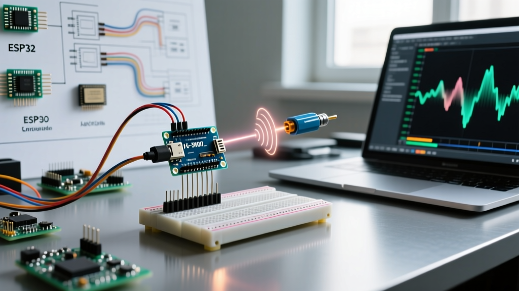
If your Arduino LED strip looks like a disco ball of random, chaotic colors, your data line is suffering from signal integrity issues. This is especially prevalent when migrating from a 5V Arduino Uno to a 3.3V microcontroller like the ESP32 or Raspberry Pi Pico.
Logic Level Mismatch
The WS2812B datasheet specifies that a logic HIGH on the DIN pin must be at least 0.7 × VDD. If VDD is 5V, the microcontroller must output a minimum of 3.5V to register a "1". A 5V Arduino Uno outputs 4.8V, which is safe. However, an ESP32 outputs exactly 3.3V. This 0.2V deficit leaves the data line in an undefined state, making it highly susceptible to electromagnetic interference (EMI) and resulting in random flickering.
The Fix: Level Shifting and Termination
- Use a 74AHCT125 Level Shifter: According to the Texas Instruments SN74AHCT125 datasheet, this specific IC accepts 3.3V logic inputs and outputs a robust 5V signal when powered by a 5V source. It is the gold standard for ESP32-to-WS2812B communication.
- The 330Ω - 470Ω Resistor: Always place a resistor directly on the DIN line, as close to the first LED as possible. This prevents high-frequency ringing (voltage overshoot) caused by long data wires, which can fry the first pixel's data-in pin.
- Data Wire Routing: Keep the data wire under 50cm. If you must run data further, use a shielded cable (like CAT5e) and connect the shield to ground at the microcontroller end only.
Issue 3: The "Dead Strip" and Boot-Up Flashes
When you power on your project, the first LED flashes blinding white, and then the entire strip goes dead. This happens because of two distinct wiring errors.
Missing the Common Ground
A data signal is not an absolute voltage; it is a potential difference measured against the ground reference. If your LED strip is powered by a dedicated 5V 10A power supply, and your Arduino is powered via USB from your laptop, their ground references may differ by a few hundred millivolts. This offset corrupts the data signal. Fix: Always run a ground wire from the Arduino GND pin directly to the negative terminal of the LED power supply.
The Inrush Current Capacitor
Addressable LEDs feature large internal decoupling capacitors. When power is applied, hundreds of LEDs attempt to charge simultaneously, creating a massive inrush current that can trip your power supply's short-circuit protection or cause a voltage brownout. As highlighted in the Adafruit NeoPixel Überguide, you must place a 1000µF electrolytic capacitor (rated for at least 10V) across the VCC and GND terminals at the power supply end. This acts as a local energy reservoir, smoothing out boot-up spikes.
Issue 4: FastLED Compilation and SRAM Limits
Sometimes the hardware is perfect, but the strip won't light up because the code never actually runs. If you are using an Arduino Uno or Nano (based on the ATmega328P chip), you are severely constrained by memory.
The 2KB SRAM Bottleneck
The ATmega328P has only 2048 bytes of SRAM. The FastLED library requires 3 bytes of SRAM per LED (one byte each for Red, Green, and Blue) to maintain the frame buffer in memory. If you define an array of 600 LEDs, you consume 1800 bytes. This leaves just 248 bytes for the Arduino's call stack, serial buffers, and local variables, resulting in silent memory corruption and a frozen microcontroller.
Software Throttling and Hardware Upgrades
If you are constrained to an Arduino Uno, limit your strip to 450 LEDs maximum. Furthermore, protect your power supply from brownouts by adding this crucial line to your FastLED setup() function:
FastLED.setMaxPowerInVoltsAndMilliamps(5, 3000);
This forces the FastLED engine to dynamically scale down the brightness of the LEDs if the calculated current draw exceeds your 3A power supply limit, preventing sudden system resets.
For installations requiring 1000+ LEDs, abandon the ATmega328P. Upgrade to an ESP32-S3 (which offers 512KB of SRAM and dual-core processing for complex animations) or a Teensy 4.1 (600MHz Cortex-M7 with 1MB RAM), both of which are the industry standards for large-scale LED mapping in 2026.
Summary Checklist for a Bulletproof Build
- [ ] Power supply rated for 60mA per LED (e.g., 5V 20A for 300 LEDs).
- [ ] 1000µF capacitor installed at the power supply terminals.
- [ ] Common ground established between MCU and LED PSU.
- [ ] 330Ω resistor on the DIN line, placed near the first pixel.
- [ ] 74AHCT125 level shifter used if MCU is 3.3V (ESP32/Pico).
- [ ] Power injected every 50-100 LEDs using 18 AWG wire.