
The 'Blinking LED of Death': Why Your Arduino GPS Won't Lock
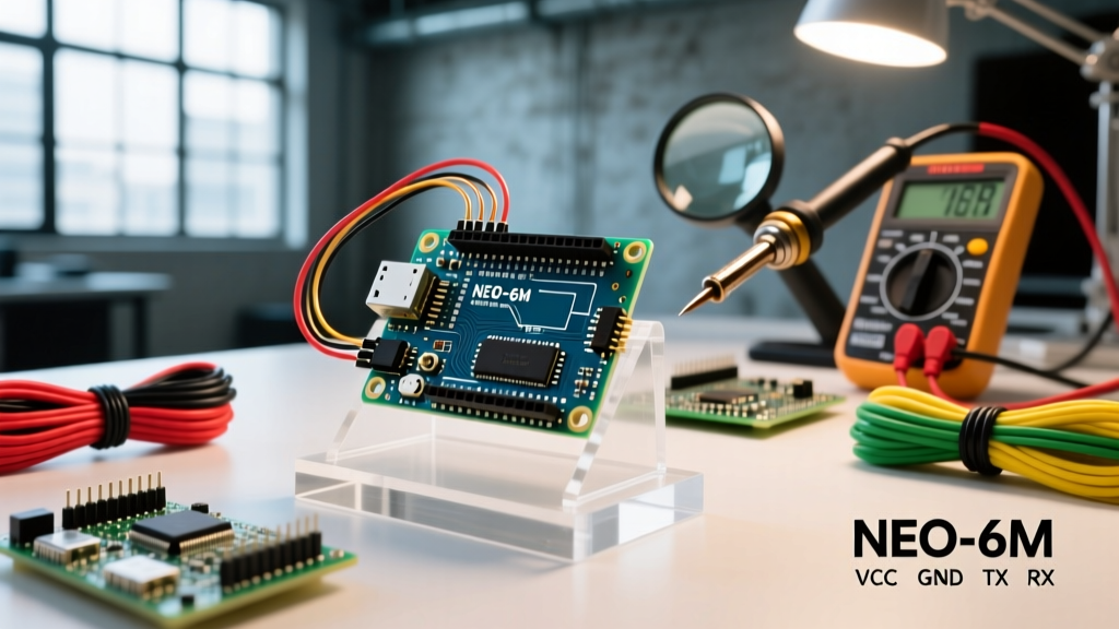
There are few things more frustrating in the maker space than wiring up a u-blox NEO-6M or NEO-M8N GPS module to an Arduino, uploading your sketch, and watching the PPS (Pulse Per Second) LED blink endlessly. A blinking LED means the module is powered and searching, but it has failed to achieve a satellite lock. If the LED never turns on, or if your Serial Monitor is vomiting garbage characters instead of clean NMEA sentences, you are dealing with a hardware, power, or serial buffer issue.
As of 2026, the market is still flooded with inexpensive $6 to $12 NEO-6M clone modules. While these are fantastic for budget projects, they frequently ship with degraded backup batteries, poorly tuned ceramic patch antennas, and voltage regulators that cannot handle cold-start current spikes. This guide bypasses the generic advice and dives deep into the exact electrical and software failure modes that prevent Arduino GPS modules from locking and parsing correctly.
Rapid Diagnostic Matrix
Before rewriting your code, use this matrix to identify your specific failure mode based on the physical behavior of the module and the Serial Monitor output.
| Symptom | Probable Root Cause | Immediate Fix |
|---|---|---|
| LED is completely OFF | Reverse polarity, dead 3.3V LDO, or insufficient current from Arduino 3.3V pin. | Verify GND/VCC. Power the module via the 5V pin (if it has an onboard AMS1117 LDO) or use an external buck converter. |
| LED blinks forever (No Lock) | Ceramic antenna obstructed, cold-start brownout, or dead EEPROM battery. | Move outdoors with clear sky view. Ensure power supply can deliver 50mA+ continuously. |
| Garbage characters in Serial Monitor | Baud rate mismatch (Module is 9600, Serial is 115200) or missing common ground. | Match SoftwareSerial baud rate to module default (usually 9600 for NEO-6M, 115200 for some M8N clones). |
| Clean NMEA data, but TinyGPS++ yields no coordinates | Missing $GPRMC or $GPGGA sentences; checksum failures dropping valid packets. | Reduce baud rate to 9600 to prevent SoftwareSerial buffer overflows. Check antenna placement. |
Phase 1: Power Rail Isolation and Cold-Start Brownouts
The most common hidden killer of GPS locks is the cold-start current spike. When a GPS module first powers on and searches for satellites (a 'cold start'), it powers up all internal RF correlators simultaneously. According to u-blox hardware specifications, a NEO-6M can draw up to 45mA during acquisition, and a NEO-M8N can spike to 50mA or more.
The Arduino 3.3V Pin Trap
Many beginners wire the GPS VCC directly to the Arduino Uno's 3.3V pin. However, the onboard 3.3V LDO on many standard Arduinos (and especially cheap clones) is only rated for 50mA to 150mA total. If you have an SD card module, an NRF24L01, or even a bright status LED sharing that 3.3V rail, the voltage will sag below 3.0V during the GPS cold start. The GPS module's internal microcontroller will brownout and reset before it can lock onto satellites, trapping it in an infinite blinking loop.
- The Fix: If your GPS module has an onboard 3.3V LDO (look for a small 3-pin SMD chip labeled 1117 or 662k), wire the module's VCC to the Arduino's 5V pin. The module will handle the regulation.
- Alternative: If your module is strictly 3.3V with no onboard regulator (like the Adafruit Ultimate GPS breakout), power it using a dedicated external 3.3V buck converter or an LDO like the LM1117-3.3 tied directly to the 5V line, bypassing the Arduino's weak internal regulator.
Phase 2: The SoftwareSerial Bottleneck and Buffer Overflows
If your Serial Monitor shows perfect $GPGGA sentences occasionally, but your TinyGPS++ library reports gps.location.isValid() == false, you are likely experiencing serial buffer overflows.
GPS modules output a massive amount of data. A standard NMEA stream at 9600 baud outputs roughly 5 to 8 sentences per second. If you initialize SoftwareSerial at 115200 baud, or if your Arduino sketch spends too much time executing blocking functions (like writing to an SD card or updating a slow I2C OLED display), the 64-byte internal buffer of the SoftwareSerial library will overflow. When bytes are dropped, the NMEA checksum at the end of the sentence becomes invalid, and the parsing library silently discards the corrupted data.
Optimizing Your Serial Configuration
To guarantee data integrity when using standard 8-bit AVR Arduinos (Uno, Nano, Mega):
- Force 9600 Baud: Never use 115200 baud with
SoftwareSerial. The AVR interrupt overhead cannot reliably catch bits at that speed while doing other tasks. Use the u-blox U-Center software or send a$PUBX,41,1,0007,0003,9600,0*13configuration string to permanently lower your module's baud rate to 9600. - Use Hardware Serial When Possible: If you are using an Arduino Mega, use
Serial1,Serial2, orSerial3. If you have migrated to an ESP32 for your 2026 projects, useHardwareSerial(UART1 or UART2) mapped to custom GPIO pins. Hardware UARTs have dedicated FIFO buffers and DMA handling that completely eliminate software byte-drop issues.
Phase 3: NMEA Parsing and Checksum Failures
The TinyGPS++ library by Mikal Hart is the industry standard for parsing NMEA data on microcontrollers. However, it is strictly dependent on receiving complete, uncorrupted sentences ending in a valid hex checksum (e.g., *5A).
If you are using SoftwareSerial, you must structure your loop() to prioritize reading the serial buffer above all else. Consider this optimized snippet:
#include <TinyGPSPlus.h>
#include <SoftwareSerial.h>

TinyGPSPlus gps;
SoftwareSerial ss(4, 3); // RX, TX

void setup() {
  Serial.begin(115200);
  ss.begin(9600); // Always match module's actual baud rate
}

void loop() {
  // Prioritize buffer clearing to prevent overflow
  while (ss.available() > 0) {
    if (gps.encode(ss.read())) {
      displayInfo();
    }
  }

  // Alert if no data has arrived for 5 seconds
  if (millis() > 5000 && gps.charsProcessed() < 10) {
    Serial.println(F("No GPS detected: Check Wiring."));
    while(true);
  }
}
Notice the while (ss.available() > 0) loop. This ensures the Arduino reads every single byte currently sitting in the hardware UART shift register and moves it into the TinyGPS++ parser before moving on to update displays or log data.
Phase 4: Antenna Physics and Environmental Blindspots
If your power is clean and your serial data is perfectly parsed, but you still have no lock, the issue is RF physics. The square ceramic patch antennas included with NEO-6M and NEO-M8N modules are Right-Hand Circularly Polarized (RHCP). They have a strict hemispherical reception pattern.
Expert Tip: A ceramic patch antenna must face the sky directly. If you mount your project in an enclosure and the antenna is facing sideways, or worse, upside down, you will experience a 20dB to 30dB signal attenuation. Furthermore, GPS L1 band signals (1575.42 MHz) cannot penetrate metal roofs, dense concrete, or wet foliage. You must test your initial lock outdoors with a direct line of sight to the sky.
According to the Adafruit Ultimate GPS learning guide, a cold start outdoors with a clear sky view should yield a lock within 1 to 2 minutes. If you are testing indoors near a window, a cold start can take 15 to 30 minutes, or fail entirely due to multipath interference bouncing off buildings.
The Backup Battery Issue
Most cheap GPS modules include a small rechargeable LIR1220 or MS621FE backup battery designed to keep the real-time clock and ephemeris data alive during power loss (Hot Start). On clone boards sitting in warehouses for years, these batteries are often completely dead or degraded. A dead backup battery forces a cold start every single time you power the Arduino. If your project is mobile and frequently powered off, consider soldering a fresh LIR1220 coin cell to the backup pads to enable hot starts, which lock in under 10 seconds.
Summary Checklist for a Perfect Lock
- Verify the module is receiving a stable 3.3V (or 5V if onboard LDO is present) capable of 50mA+ continuous draw.
- Ensure
SoftwareSerialis strictly limited to 9600 baud to prevent buffer overflows and NMEA checksum drops. - Confirm the ceramic patch antenna is facing directly upward with an unobstructed view of the sky.
- Use
HardwareSerialon Mega or ESP32 boards for mission-critical logging where zero data loss is acceptable.
By systematically isolating the power delivery, respecting the limitations of software-based UARTs, and understanding the physical requirements of RHCP antennas, you can transform a frustrating, blinking GPS module into a highly accurate tracking asset. For deeper dives into serial communication limits, refer to the official Arduino SoftwareSerial documentation to understand the exact interrupt timing constraints of AVR microcontrollers.