
The 'Ghost Input' Phenomenon: Why Floating Pins Fail
When building circuits with tactile switches, reed relays, or digital sensors, encountering erratic behavior on the serial monitor is a frustrating rite of passage. You press a button once, but the Arduino registers three presses, or the pin triggers randomly when you simply wave your hand over the breadboard. This 'ghost input' phenomenon is almost always traced back to a single hardware omission: the lack of an arduino pull down resistor. In this diagnostic guide, we bypass basic tutorials and dive deep into the CMOS physics, microcontroller architecture limitations, and multimeter-level troubleshooting required to permanently eliminate floating pin errors.
The Physics of Floating Pins and CMOS Antennas
To diagnose a floating pin error, you must first understand the underlying semiconductor physics. The digital input pins on standard microcontrollers like the ATmega328P (used in the Arduino Uno and Nano) utilize CMOS (Complementary Metal-Oxide-Semiconductor) logic gates. These gates possess an extraordinarily high input impedance—often exceeding 10^12 ohms. According to the Microchip ATmega328P Datasheet, the maximum input leakage current is a mere ±1µA.
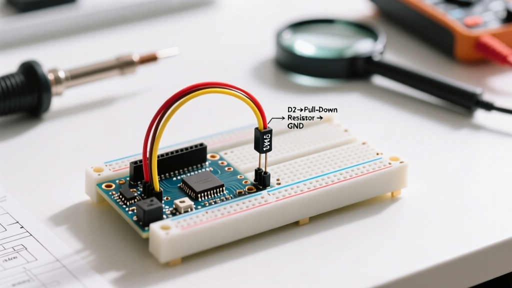
Because the pin draws virtually zero current, an unconnected (floating) pin acts as a high-impedance antenna. It readily couples with ambient electromagnetic interference (EMI), 50/60Hz mains hum, and stray capacitance from adjacent wires. When the accumulated charge on the pin's parasitic capacitance crosses the microcontroller's logic threshold (typically 0.3 VCC for LOW and 0.6 VCC for HIGH), the digital input flips states erratically. An arduino pull down resistor provides a deliberate, low-impedance path to ground (0V), bleeding off this stray charge and forcing the pin to a definitive LOW state when the switch is open.
The AVR Internal Pull-Down Myth (Crucial Architecture Error)
One of the most common diagnostic dead-ends for beginners is attempting to use software to solve a hardware architecture limitation. Many makers write the following code, expecting the internal resistor to engage:
pinMode(2, INPUT_PULLDOWN);On a standard Arduino Uno, Nano, or Mega, this is a critical error. The AVR architecture (ATmega328P/2560) features internal pull-up resistors (typically 20kΩ to 50kΩ), but it does not possess internal pull-down resistors. If you attempt to use a pull-down configuration on an AVR chip without an external physical resistor, your pin will float, resulting in the exact ghost inputs you are trying to prevent.
Architecture Note: ESP32 vs. AVR
If you migrate your design to an ESP32 (Xtensa LX6 architecture), the rules change. The ESP32 GPIO matrix does include internal pull-down resistors alongside pull-ups. However, relying on internal resistors for long wire runs or high-EMI environments is still poor engineering practice due to their weak resistance values. For robust industrial or automotive DIY designs, external discrete resistors remain the gold standard. For more on pin configurations, refer to the Arduino Digital Pins Documentation.
Diagnostic Protocol: Proving a Pin is Floating
Before soldering or modifying your breadboard, use this step-by-step diagnostic protocol to confirm that a missing or failing pull-down resistor is the root cause of your logic errors.
- Visual Ground Continuity Check: Use a multimeter in continuity mode to verify that the ground rail of your breadboard is actually connected to the Arduino's GND pin. A surprisingly common breadboard fault is a split ground rail that leaves the pull-down resistor referencing a floating node instead of true ground.
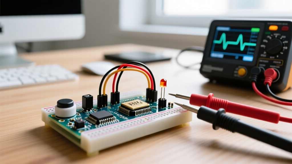
- DC Voltage Measurement (Switch Open): Set your multimeter to DC Voltage. Place the black probe on Arduino GND and the red probe on the digital input pin. With the switch open, a healthy pull-down circuit will read 0.00V to 0.05V. If the reading fluctuates randomly between 0.5V and 2.5V, the pin is floating.
- Oscilloscope AC Ripple Analysis: If a multimeter shows a stable but incorrect voltage (e.g., 1.2V), connect an oscilloscope. A floating pin in a typical maker space will display a 50Hz or 60Hz sine wave (mains hum) or high-frequency switching noise from nearby SMPS (Switch Mode Power Supplies) exceeding 100mV peak-to-peak. A properly sized pull-down resistor will flatten this trace to a clean DC line near 0V.
- Resistor Continuity Test: Power down the circuit. Measure the resistance between the input pin and GND. You should read the exact value of your pull-down resistor (e.g., 10.0kΩ). If you read OL (Open Loop), the resistor is unseated, the jumper wire is broken, or the breadboard contact has failed.
Sizing the Arduino Pull Down Resistor: The 10kΩ Rule vs Reality
The maker community defaults to 10kΩ for almost every pull-up and pull-down application. While 10kΩ is a safe baseline, understanding why it works—and when you need to deviate—is the hallmark of advanced error diagnosis. The goal is to select a resistance low enough to overpower stray EMI, but high enough to prevent excessive current draw when the switch is closed.
According to Texas Instruments Application Report SCBA004 on floating CMOS inputs, the resistor must provide sufficient current to overcome the input leakage and stray capacitive coupling, ensuring the voltage never breaches the logic LOW threshold (VIL).
| Resistance | Current Draw (Switch Closed) | Noise Immunity | Power Dissipation | Diagnostic Verdict |
|---|---|---|---|---|
| 100Ω | 50.0 mA | Excellent | 250 mW | Avoid: Wastes battery life and exceeds the 40mA absolute max limit of some smaller switches. |
| 1kΩ | 5.0 mA | Very High | 25 mW | Use for: High-EMI environments, automotive applications, or long cable runs (>1 meter). |
| 10kΩ | 0.5 mA | Good | 2.5 mW | Standard: Ideal for breadboards, short jumper wires, and standard battery-powered projects. |
| 100kΩ | 0.05 mA | Poor | 0.25 mW | Risky: Susceptible to stray capacitance and finger-induced ghost triggers on standard breadboards. |
| 1MΩ | 0.005 mA | Terrible | 0.025 mW | Fault: Will almost certainly result in floating pin errors due to CMOS leakage and ambient RF. |
Edge Cases: Long Wires, EMI, and Stray Capacitance
If you have verified your wiring, confirmed you are using an external resistor (since AVR lacks internal pull-downs), and are still experiencing ghost inputs, you are likely dealing with parasitic capacitance. Every wire possesses a small amount of capacitance relative to its environment. A standard breadboard jumper wire has roughly 2pF to 5pF of capacitance. However, if you are routing a sensor cable that is 2 meters long, that capacitance can easily exceed 100pF.
When a long wire acts as a capacitor, it stores charge. If your pull-down resistor is too weak (e.g., 100kΩ), the RC time constant (τ = R × C) becomes large enough that high-frequency EMI spikes can momentarily push the pin voltage above the 1.5V logic LOW threshold before the resistor can bleed the charge to ground.
The Hardware Fix for Long Cable Runs
To diagnose and fix this specific edge case, drop your arduino pull down resistor value from the standard 10kΩ down to 2.2kΩ or 4.7kΩ. This lowers the impedance of the ground path, drastically reducing the RC time constant and effectively 'shorting out' high-frequency noise before the microcontroller's logic gate can sample it. Additionally, for runs exceeding 3 meters, abandon simple digital read logic and implement a hardware Schmitt trigger (like the 74HC14) or use a differential signaling standard like RS-485.
Summary of Diagnostic Best Practices
Eliminating floating pin errors requires moving beyond copy-pasted code and understanding the physical layer of your circuit. Always remember that standard AVR Arduinos require physical, external resistors to pull a pin to ground. By utilizing a multimeter to verify ground continuity, an oscilloscope to identify EMI coupling, and selecting a resistor value mathematically matched to your wire length and environmental noise, you can achieve rock-solid digital input stability in any environment.