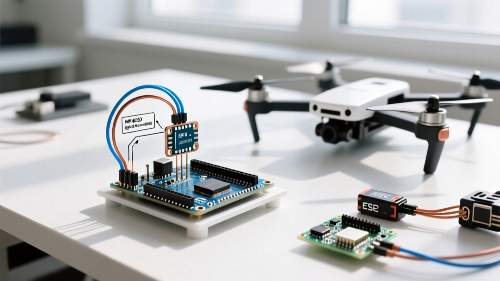

Why Build a Drone with an Arduino in 2026?
In 2026, while 32-bit F7 and H7 flight controllers running highly optimized Betaflight or ArduPilot firmware dominate the commercial and FPV markets, building a custom quadcopter using an Arduino as flight controller remains the ultimate rite of passage for robotics engineers and embedded systems students. Off-the-shelf stacks abstract away the complex mathematics of sensor fusion and motor control. By stripping away the black box and relying on an 8-bit ATmega328P microcontroller, you are forced to confront the raw physics of flight: I2C bus arbitration, discrete PID control loops, PWM signal generation, and high-frequency vibration aliasing.
This guide bypasses basic blink sketches and dives straight into the engineering realities of stabilizing a 4-rotor aircraft using an Arduino Nano and an MPU6050 Inertial Measurement Unit (IMU).
Hardware Bill of Materials (BOM)
Choosing the right components is critical. The ATmega328P operates at 16MHz with only 2KB of SRAM, meaning we cannot run heavy floating-point math or complex Kalman filters. We must rely on efficient integer math and fast sensor polling.
| Component | Specific Model / Value | Estimated Cost | Engineering Notes |
|---|---|---|---|
| Microcontroller | Arduino Nano (ATmega328P, 16MHz) | $6.00 | Clone boards with CH340 USB chips are fine, but ensure the 5V logic regulator is robust. |
| IMU Sensor | GY-521 Breakout (MPU-6050) | $4.50 | Combines 3-axis gyro and 3-axis accelerometer. Requires 3.3V power but tolerates 5V I2C logic. |
| Power Supply | 5V 3A UBEC (Switching Regulator) | $8.00 | Mandatory. Do not use the Nano's onboard linear regulator for high-current servo/ESC logic. |
| Motors | Emax RS2205 2300KV Brushless | $18.00 ea | High KV requires aggressive PID derivative tuning to prevent oscillation. |
| ESCs | 30A SimonK or BLHeli_S (No DShot) | $12.00 ea | Must support standard 50Hz PWM (1000-2000µs pulse width). |
Step 1: Power Distribution and Brownout Prevention
The most common cause of failure in DIY Arduino drones is a mid-flight brownout. A standard 4S LiPo battery outputs 14.8V nominally and up to 16.8V when fully charged. The Arduino Nano features an onboard AMS1117-5.0 linear voltage regulator. If you feed 16.8V into the Vin pin, the regulator must dissipate nearly 12V as heat to step it down to 5V. Under the current draw of an active I2C bus and PWM generation, the AMS1117 will rapidly hit its thermal shutdown threshold (around 150°C junction temperature), causing the microcontroller to reboot mid-air.
Expert Rule: Never power an Arduino flight controller directly from a battery voltage exceeding 12V via the Vin pin. Always use a dedicated 5V 3A UBEC (Universal Battery Eliminator Circuit) wired directly to the Arduino's5VandGNDpins, completely bypassing the onboard regulator.
Step 2: IMU Integration and I2C Bus Stabilization
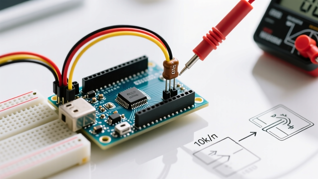
The TDK InvenSense MPU-6050 communicates via I2C. On the Arduino Nano, the hardware I2C pins are A4 (SDA) and A5 (SCL). While the GY-521 breakout board includes some surface-mount pull-up resistors, they are often too weak (10kΩ or higher) to maintain signal integrity in the electrically noisy environment of a quadcopter, where brushless motor EMF interference is rampant.
Hardware I2C Stabilization
- Add Pull-Up Resistors: Solder 4.7kΩ resistors between the SDA and 3.3V lines, and the SCL and 3.3V lines. This stiffens the I2C bus and prevents the Arduino Wire library from hanging indefinitely if a noise spike corrupts a byte.
- Vibration Isolation: High-frequency motor vibrations (often >100Hz) will alias into the MPU6050's accelerometer, creating low-frequency noise that the PID controller interprets as physical tilt. Mount the Arduino and IMU to the frame using 3mm silicone O-rings (Shore A durometer ~30) to act as a mechanical low-pass filter.
- Loop Rate Configuration: Configure the MPU6050's internal Digital Low Pass Filter (DLPF) to 44Hz bandwidth. This introduces a slight phase delay but drastically reduces high-frequency noise before the data even reaches the ATmega328P.
Step 3: ESC Calibration and PWM Signal Generation
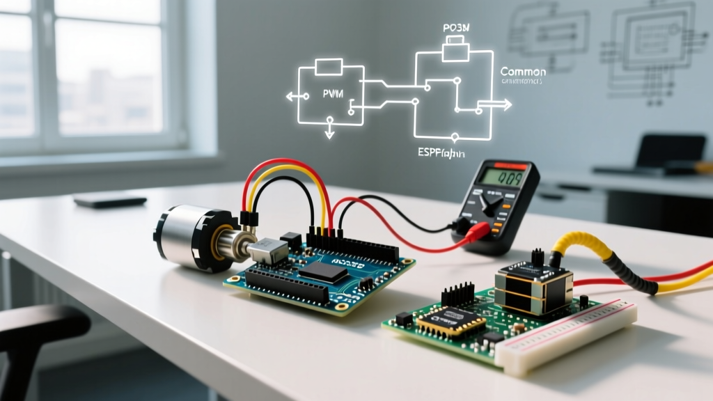
Brushless Electronic Speed Controllers (ESCs) expect a standard 50Hz PWM signal, where the pulse width dictates the throttle. A 1000µs pulse means zero throttle (motor stop), and a 2000µs pulse means 100% throttle. The Arduino Servo Library is perfectly suited for generating these pulses using the chip's hardware timers.
The Arming Sequence
ESCs will not spin if they do not detect a valid zero-throttle signal upon power-up. Your setup() function must include an arming sequence:
- Attach the ESC signal pins to the Arduino Servo objects.
- Write a value of
1000(1000µs) to all four ESCs. - Delay for exactly 2000 milliseconds to allow the ESCs to read the signal and arm their internal safety circuits.
- Listen for the confirmation beep sequence from the motors.
Step 4: Architecting the PID Control Loop
The core of using an Arduino as a flight controller is the Proportional-Integral-Derivative (PID) algorithm. Because the ATmega328P struggles with heavy floating-point operations, you should implement the PID loop using integer math, scaling your sensor readings by a factor of 100 or 1000 to preserve decimal precision.
Fixed-Timing Execution
A PID controller must execute at a strictly fixed time interval (Delta Time, or dt). If your loop time fluctuates because of I2C read delays or serial printing, the Derivative and Integral terms will calculate incorrectly, leading to violent motor oscillations.
Do not use the delay() function. Instead, use a blocking while() loop tied to the micros() timer to enforce a rigid 4-millisecond (250Hz) loop rate:
unsigned long currentMicros = micros();
while (micros() - currentMicros < 4000) {
  // Wait for the next 4ms cycle
}
// Execute IMU read and PID math here
Tuning Methodology for Arduino Drones
Without the luxury of Betaflight's auto-tune or graphical PID sliders, you must tune manually via Serial Monitor telemetry:
- Proportional (P): Set I and D to zero. Increase P until the drone wobbles rapidly on an axis, then reduce it by 20%. This gives you the baseline responsiveness.
- Derivative (D): D acts as a damper against rapid changes (noise and sudden stick inputs). Increase D until the motors become hot to the touch or emit a high-pitched whine, then back off by 30%. This term is highly sensitive to the IMU vibration isolation you performed in Step 2.
- Integral (I): I corrects steady-state errors (like a drone drifting due to a slightly off-center center of gravity). Increase I just enough to stop slow, wandering drifts. Too much I will cause 'ballooning' at the end of fast maneuvers.
Edge Cases and Mid-Flight Failure Modes
When deploying an 8-bit microcontroller in a safety-critical aerospace application, you must engineer around its limitations. Below is a matrix of common failure modes and their hardware/software mitigations.
| Failure Mode | Root Cause | Engineering Mitigation |
|---|---|---|
| I2C Bus Lockup | EMI causes SDA line to stick LOW, freezing the Wire library. |
Implement a hardware Watchdog Timer (WDT) that resets the MCU if the main loop hangs for more than 50ms. |
| Integral Windup | Drone flips, PID I-term accumulates massive error, motors stay at 100% even when upright. | Hard-clamp the I-term variable in software. Disable the I-term entirely if the quadcopter tilt angle exceeds 45 degrees. |
| Gyro Saturation | Acrobatic flip exceeds the MPU6050's default ±250°/sec range. | Configure the MPU6050 gyro scale to ±2000°/sec via register 0x1B during initialization. |
Conclusion
Using an Arduino as a flight controller is not about competing with modern, $60 commercial flight stacks that run 32kHz PID loops and RPM filtering. It is about achieving a fundamental mastery of embedded robotics. By managing your own I2C pull-ups, writing fixed-timer interrupt routines, and manually deriving your PID constants, you transition from being a consumer of drone technology to a true aerospace systems engineer. Ensure your wiring is secured with hot glue, double-check your motor spin directions, and always conduct your first PID tests with the propellers removed and the quadcopter tethered to a heavy workbench.