
The ESP32-C3 Mini has rapidly become a staple on the workbenches of IoT developers and Arduino hobbyists. Serving as the spiritual and practical successor to the legendary ESP8266, this compact development board brings modern security, Bluetooth 5 (LE), and a fundamentally different CPU architecture to the maker community. However, beneath its familiar breadboard-friendly footprint lies a set of hardware quirks, USB-bridge lotteries, and strapping pin traps that can easily frustrate beginners.
Whether you are migrating from an older NodeMCU board or designing a low-cost commercial IoT sensor, understanding the silicon and the supporting circuitry of the ESP32-C3 Mini is critical. This concept explainer breaks down the RISC-V architecture, hardware realities, and the exact Arduino IDE configurations required to master this microcontroller.
The RISC-V Shift: What Makes the ESP32-C3 Different?
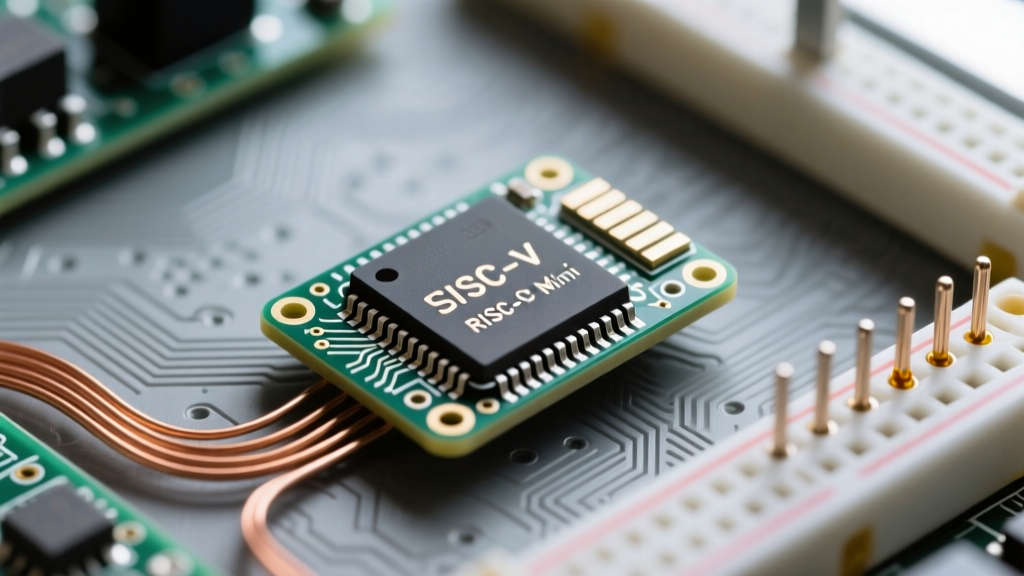
For years, Espressif relied on the Xtensa instruction set architecture (ISA) for its ESP8266 and classic ESP32 chips. The ESP32-C3 marks a massive pivot: it is powered by a 32-bit RISC-V single-core microcontroller running at up to 160 MHz. Specifically, it utilizes the RV32IMC ISA, which includes base integer operations (I), hardware multiplication and division (M), and compressed instructions (C) to reduce code size.
Why does this matter to a maker? First, RISC-V is an open-standard ISA. By eliminating Xtensa licensing fees, Espressif drastically reduced the Bill of Materials (BOM) cost. This is why you can find generic ESP32-C3 Mini boards on AliExpress for roughly $2.50, while official Wemos/Lolin C3 Mini boards hover around $4.00. Second, the RISC-V core offers a more predictable interrupt latency and a cleaner memory protection model compared to the older Xtensa cores.
Expert Insight: While the single-core 160 MHz RISC-V chip lacks the raw parallel processing power of the dual-core Xtensa ESP32, its single-threaded performance is highly optimized. For 90% of sensor-reading and Wi-Fi-transmitting IoT tasks, the C3 outperforms the ESP8266 while consuming significantly less power during active transmission.
Hardware Anatomy and the USB Bridge Lottery
The "Mini" form factor typically refers to boards modeled after the Wemos D1 Mini footprint or ultra-compact stick formats like the Seeed XIAO. However, when buying generic ESP32-C3 Mini boards, you must navigate what the community calls the "USB Bridge Lottery."
Native USB vs. External UART
The ESP32-C3 silicon features a built-in USB Serial/JTAG controller mapped to GPIO18 (D-) and GPIO19 (D+). High-quality boards leverage this native USB, eliminating the need for an external USB-to-UART bridge chip. This reduces board cost and allows for native USB HID (keyboard/mouse) emulation.
However, many budget manufacturers still solder a CH340C or CP2102 chip onto the board and wire it to the standard UART0 pins (GPIO20 RX, GPIO21 TX). If you buy a board without checking the schematic, you might attempt to flash it using CDC (Communication Device Class) protocols, only to realize the board requires standard UART serial drivers. Always inspect the PCB: if you see a secondary 16-pin or 20-pin SMD chip near the USB-C port, you have an external bridge.
ESP32-C3 Mini vs. Classic Alternatives
To understand where the C3 Mini fits in your project architecture, compare its silicon specifications against the legacy boards it aims to replace.
| Feature | ESP32-C3 Mini | ESP8266 (NodeMCU V3) | Classic ESP32 (DevKit V1) |
|---|---|---|---|
| Architecture | RISC-V 32-bit (Single-Core) | Xtensa L106 (Single-Core) | Xtensa LX6 (Dual-Core) |
| Clock Speed | 160 MHz | 80 / 160 MHz | 240 MHz |
| SRAM | 400 KB | ~50 KB usable | 520 KB |
| Wireless | Wi-Fi 4 + Bluetooth 5 (LE) | Wi-Fi 4 Only | Wi-Fi 4 + Bluetooth 4.2 (Classic/BLE) |
| ADC Resolution | 12-bit (Single Channel) | 10-bit (Single Channel) | 12-bit (Multi-Channel) |
| Typical Price | $2.50 - $4.00 | $2.00 - $3.50 | $4.50 - $6.00 |
The Strapping Pin Trap: Common Bootloader Failures
One of the most frequent failure modes encountered by makers using the ESP32-C3 Mini involves boot loops caused by strapping pins. Strapping pins are sampled by the internal bootloader during a hardware reset to determine the chip's boot mode.
According to the official Espressif ESP32-C3 Datasheet, GPIO8 and GPIO9 are the primary boot mode strapping pins. To execute your Arduino sketch normally from the SPI flash, GPIO8 must be sampled as LOW during reset. If GPIO8 is HIGH, the chip enters the ROM Serial Bootloader (download mode).
The Button Wiring Mistake
Imagine you wire a momentary pushbutton to GPIO8 to act as a user input, connecting the other side of the button to 3.3V. If that button is pressed exactly when the board resets (or if the pin is left floating and picks up EMI, reading HIGH), the ESP32-C3 will bypass your code and wait for a serial firmware upload. Your sketch will appear to have "crashed," but in reality, the hardware is waiting for a new binary.
The Fix: Never use GPIO8 or GPIO9 for inputs that can pull the pin HIGH during startup. If you must use them, ensure a strong 10kΩ pull-down resistor to GND is present, and use a debouncing capacitor to prevent transient spikes during the boot sequence.
Arduino IDE Setup and Board Manager Nuances
Flashing the ESP32-C3 Mini requires specific configurations within the Arduino IDE, particularly regarding the Espressif Arduino Core. Because of the USB bridge lottery mentioned earlier, your IDE settings must match your physical board's hardware.
- Install the Core: In the Arduino IDE Boards Manager, search for
esp32and install the latest version (v2.x or v3.x). - Select the Board: Navigate to Tools > Board and select ESP32C3 Dev Module. (Do not select a specific third-party brand unless explicitly listed, as the generic Dev Module exposes all necessary menus).
- Configure USB CDC On Boot:
- If your board has Native USB (No CH340 chip): Set
USB CDC On Bootto Enabled. This routesSerial.print()over the USB D+/D- pins. - If your board has a CH340/CP2102 chip: Set
USB CDC On Bootto Disabled. If you enable this on a board with an external UART bridge, the IDE will fail to open the serial port, and you will receive a "Failed to connect" error.
- If your board has Native USB (No CH340 chip): Set
- Flash Mode: Always leave this on QIO for standard SPI flash chips found on Mini boards.
Power Consumption: The Deep Sleep Reality Check
The ESP32-C3 is heavily marketed for battery-powered IoT applications. The ESP-IDF Hardware Reference states that the silicon itself can achieve deep sleep currents of roughly 40 μA. However, makers frequently measure 2 mA to 5 mA on their multimeters and assume the chip is defective.
The culprit is not the RISC-V silicon; it is the "Mini" development board's supporting circuitry. To achieve true microamp-level deep sleep, you must overcome three hardware hurdles:
- The Power LED: Most C3 Mini boards feature a power indicator LED tied directly to the 3.3V rail. This LED alone will draw 2-5 mA continuously. You must desolder it or cut the PCB trace.
- The LDO Quiescent Current: Budget boards use cheap Linear Dropout Regulators (like the ME6211 or AMS1117) to drop 5V USB to 3.3V. These LDOs have a quiescent current (Iq) of 1 mA to 5 mA even when the ESP32 is asleep. For battery projects, bypass the onboard LDO and power the 3.3V pin directly from a low-Iq external regulator or a 3.7V LiPo (if the board tolerates 4.2V on the 3.3V rail, though this is risky and requires checking the specific capacitor voltage ratings).
- GPIO Leakage: In deep sleep, any GPIO pin configured as HIGH will leak current into connected sensors. Ensure all external peripherals are powered via a dedicated GPIO acting as a high-side MOSFET switch, completely cutting power to sensors before entering
esp_deep_sleep_start().
Final Verdict for Makers
The ESP32-C3 Mini is a masterclass in cost-effective IoT design. By embracing the RISC-V ecosystem, Espressif has delivered a board that bridges the gap between the outdated ESP8266 and the overpowered, dual-core classic ESP32. By understanding the nuances of its USB routing, respecting the strapping pins, and properly engineering your power delivery network, the C3 Mini is arguably the best general-purpose microcontroller board available for modern connected projects.