
Introduction: The Hidden Dangers of Arduino Power Routing
Figuring out how to power an Arduino board seems deceptively simple until you fry a voltage regulator or trigger an endless brownout reset loop. As microcontrollers have evolved from the classic ATmega328P-based Uno R3 to the ARM Cortex-M4 powered Uno R4 Minima and WiFi, the power delivery architectures have shifted dramatically. Yet, the forums are still flooded with makers asking why their 12V solenoid projects keep resetting, or why their onboard regulators are too hot to touch.
In this community resource roundup, we have synthesized years of hard-won insights from the Arduino Forum, EEVblog, and professional electrical engineering guides to map out exactly how to route power to your projects. We will cover the five primary power injection methods, the thermal mathematics of linear regulators, and the modern switching alternatives that the community swears by in 2026.
The 5 Ways to Power an Arduino: Community Comparison Matrix
Before diving into the schematics, review this quick-reference matrix. It highlights the operational boundaries for standard 5V Arduino boards (like the Uno R3 and R4 series).
| Power Method | Acceptable Voltage Range | Max Recommended Current | Risk Level | Best Use Case |
|---|---|---|---|---|
| USB Port (Type-B / Type-C) | 4.75V - 5.25V | 500mA (USB 2.0) / 900mA (USB 3.0) | Low | Desktop prototyping, low-power sensor logging |
| DC Barrel Jack (2.1mm) | 7V - 12V (Absolute max 20V) | ~300mA (at 9V in) | Medium-High | Standalone 9V battery projects, basic motor shields |
| Vin Pin | 7V - 12V | ~300mA (at 9V in) | Medium-High | Custom PCBs with external barrel jacks |
| 5V Pin (Direct Injection) | 4.8V - 5.5V (5.0V ideal) | Limited by trace width (typically 1A) | Critical (No protection) | High-current LED strips, custom 5V buck supplies |
| 3.3V Pin | 3.3V Exact | 50mA (R3) / 1000mA (R4) | Medium | ESP8266/ESP32 companion modules, low-power radios |
Method 1: USB Power (The Safest Starting Point)
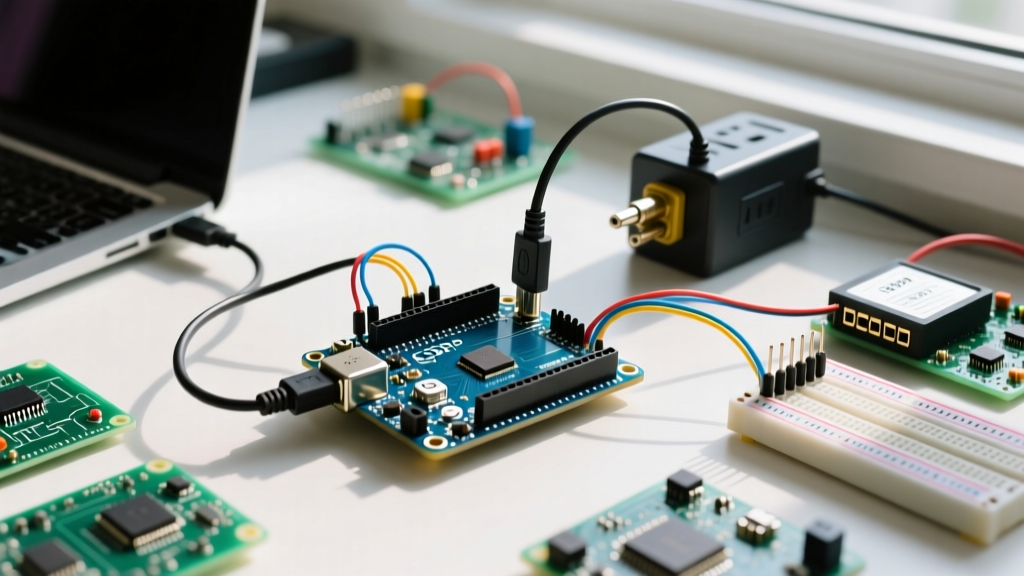
Powering via USB is the universal starting point. On the classic Uno R3, the USB-B connector routes 5V through a 500mA resettable PTC polyfuse before hitting the 5V rail. On the newer Uno R4 series, the USB-C port handles power negotiation, but the fundamental 5V rail limits remain tied to the host port's capabilities.
The 'Ghost Power' Edge Case
A frequent community trap occurs when makers back-power the board through a shield's 5V pin while the USB is also connected. The Arduino Uno features an auto-voltage selector circuit (often utilizing an LMV358 op-amp and a P-channel MOSFET) that compares the USB 5V with the barrel jack/Vin voltage. If the USB voltage is higher than the Vin-derived 5V, the MOSFET opens to prevent back-feeding the regulator. However, injecting 5.5V into the 5V pin while plugged into a 4.8V USB port can confuse this comparator, potentially damaging the USB host controller on your PC.
Method 2: The Barrel Jack & The Thermal Trap
The 2.1mm center-positive barrel jack is designed for wall warts ranging from 7V to 12V. The raw voltage passes through a protection diode (D1, typically a 1N4007) and feeds the onboard linear regulator. On the Uno R3, this is the NCP1117ST50T3G, a 5V linear regulator in a SOT-223 surface-mount package.
According to SparkFun's Guide to Voltage Regulators, linear regulators operate by burning off excess voltage as heat. This is where most makers destroy their boards.
The Thermal Mathematics of Failure
Let us calculate the exact thermal limits using the community-standard formula for power dissipation ($P_d$):
$P_d = (V_{in} - V_{out}) \times I_{load}$
Assume you plug in a 12V wall adapter ($V_{in} = 12V$) to power your Arduino and a string of WS2812B LEDs drawing 300mA ($0.3A$) from the 5V pin.
- Voltage Drop: $12V - 5V = 7V$
- Power Dissipated: $7V \times 0.3A = 2.1W$
The SOT-223 package has a junction-to-ambient thermal resistance ($R_{\theta JA}$) of approximately $50^\circ C/W$ without a heatsink. Multiplying $2.1W \times 50^\circ C/W$ yields a temperature rise of $105^\circ C$ above ambient. In a standard $25^\circ C$ room, the silicon junction hits $130^\circ C$. The NCP1117's internal thermal shutdown triggers at $150^\circ C$. You are now millimeters away from the board shutting down, resetting, and entering a permanent thermal hiccup loop.
Community Consensus: Never use the barrel jack if your 5V rail current draw exceeds 150mA at 12V input. Stick to 7V-9V inputs to minimize the thermal gradient.
Method 3: The Vin Pin (Bypassing the Jack)
The Vin (Voltage Input) pin is electrically identical to the barrel jack's input, just after the protection diode D1. It is heavily used in custom PCB shields where routing a massive DC barrel jack is impractical.
Warning: While the barrel jack has the D1 diode to protect against reverse polarity, injecting voltage directly into the Vin pin on some third-party Arduino clones bypasses reverse-polarity protection depending on the board's specific trace routing. Always verify your clone's schematic before using Vin in automotive or battery-powered environments where voltage spikes and polarity swaps are common.
Method 4: The 5V Pin (Direct Injection - High Risk)
If you need to drive high-current loads like stepper motors, large servo arrays, or hundreds of addressable LEDs, the community unanimously recommends bypassing the linear regulator entirely by injecting a regulated 5V directly into the 5V pin.
Critical Failure Modes
- No Regulation: The 5V pin connects directly to the board's 5V trace. If your external supply outputs 6V due to poor load regulation, you will instantly overvoltage the ATmega328P or Renesas RA4M1, destroying the silicon.
- No Reverse Polarity Protection: Swapping Ground and 5V on the header will short your supply and fry the board's ground traces before your external supply's protection kicks in.
- USB Backfeed: If you inject 5V into the 5V pin while the USB is connected to a PC, the external 5V will backfeed into the USB port, potentially damaging your computer's USB hub.
To mitigate this, expert makers use a Schottky diode (like the 1N5819) on the external 5V line to prevent backfeeding, and ensure their power supply is a high-quality, regulated switching unit.
Community Favorites: 2026 Buck Converter Recommendations
Because linear regulators are so inefficient for battery and high-voltage projects, the maker community has largely migrated to switching step-down (buck) converters. As detailed in the Pololu Voltage Regulator Guide, switching regulators achieve 85-95% efficiency, meaning a 12V to 5V conversion at 1A draws less than 0.5A from the battery and generates almost zero heat.
Top Tier Modules for High-Current Projects
- Pololu D36V28F5 (~$12.95): A powerhouse step-down regulator accepting up to 36V in and outputting a rock-solid 5V at up to 2.8A. It features built-in over-current and over-temperature protection. Perfect for injecting directly into the Arduino 5V pin.
- Mean Well IRM-03-5 (~$8.50): For IoT projects requiring direct AC mains power. This is a fully encapsulated, UL-certified AC-DC module that solders directly to a custom shield, outputting 3W of isolated 5V DC. It completely eliminates the need for bulky external wall warts.
- Generic LM2596 Modules (~$2.00 each in bulk): The budget community staple. While they require manual trimming with a multimeter and a small screwdriver to set the output to exactly 5.0V, they are ubiquitous and handle up to 2A reliably if given adequate airflow.
Troubleshooting: The Dreaded Brownout Reset Loop
If your Arduino randomly resets when a relay clicks or a motor spins, you are experiencing a brownout. The ATmega328P has a Brown-Out Detection (BOD) circuit typically set to 2.7V or 4.3V. When a high-current inductive load activates, it pulls the 5V rail down momentarily. If it dips below the BOD threshold, the MCU resets to protect memory corruption.
The Community Fix
Do not try to fix this with software. You must fix the power delivery impedance. Solder a low-ESR electrolytic capacitor (470µF to 1000µF, 10V rated) and a 100nF ceramic capacitor in parallel directly across the 5V and GND pins of your high-current load, not just at the Arduino headers. This provides a localized energy reservoir to handle microsecond current spikes without sagging the main voltage rail.
Final Thoughts on Power Architecture
Understanding how to power an Arduino board is fundamentally about understanding thermal limits and current pathways. While the barrel jack is fine for a simple blinking LED circuit, any modern project involving wireless telemetry, motor control, or dense LED matrices demands a dedicated external switching regulator feeding the 5V pin. By respecting the physics of the onboard linear regulators and utilizing modern buck converters, you will eliminate the most common hardware failure modes and ensure your projects run reliably in the field.
For further reading on managing heat in linear regulator designs, refer to the Texas Instruments Thermal Design Guidelines for SOT-223 and similar packages.