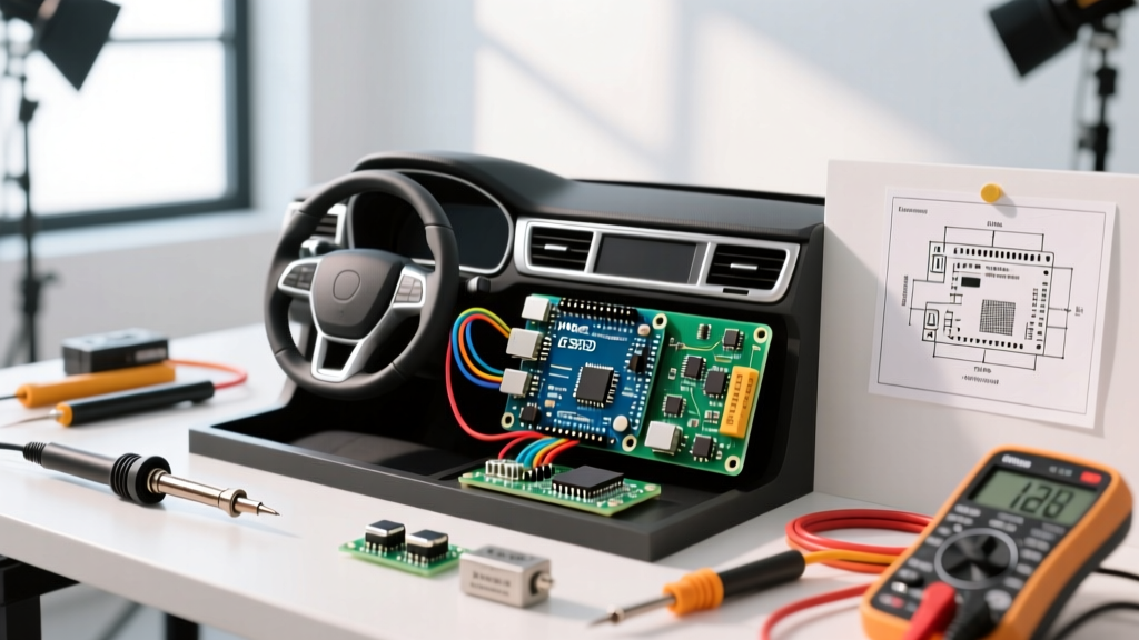

The Hostile Reality of Automotive Electrical Systems
Integrating an Arduino in the car opens up incredible possibilities for custom telemetry, OBD-II data logging, and automated cabin controls. However, the automotive electrical environment is notoriously hostile to sensitive 5V microcontroller logic. Many makers make the critical mistake of simply plugging an Arduino Uno into a USB car charger or the 12V cigarette lighter socket via the onboard barrel jack. In 2026, with vehicles featuring increasingly complex alternators and regenerative braking systems, this approach is a guaranteed path to hardware failure.
The nominal 12V system in a running car actually fluctuates between 13.5V and 14.4V. More dangerously, it is plagued by massive voltage transients. If you rely on the Arduino Uno’s onboard NCP1117 linear voltage regulator to drop 14V down to 5V, you are asking it to dissipate massive amounts of heat. At a modest 500mA draw, the regulator must burn off 4.5 watts of power. Given the SOT-223 package's thermal resistance of roughly 50°C/W, the junction temperature will spike by over 225°C, triggering an immediate thermal shutdown or permanently frying the silicon.
⚠️ Critical Warning: Never power an Arduino in an automotive environment using the onboard linear regulator or a cheap, unbranded USB step-down charger. Engine cranking can drop system voltage to 6V (causing brownouts and memory corruption), while a 'load dump' event can send 40V+ spikes through the 12V rail, instantly destroying your microcontroller.
Understanding ISO 7637-2 Automotive Transients
To design a reliable power circuit, you must understand the standard disturbances defined by ISO 7637-2. According to Texas Instruments' automotive power design guidelines, modern vehicle power rails are subjected to specific transient pulses that your power supply must survive.
| Pulse Type | Cause | Voltage Spike | Duration |
|---|---|---|---|
| Pulse 1 | Inductive load switching (e.g., wiper motors) | -25V to -100V | Microseconds |
| Pulse 2a | Load dump (alternator charging, battery disconnect) | +37V to +112V | Up to 400ms |
| Pulse 3a/3b | Fast transient bursts (switch bouncing) | -75V to +50V | Nanoseconds |
Bill of Materials (BOM) for Automotive Power
To survive these conditions, we will bypass the Arduino's internal regulator entirely and build a robust, external automotive-grade power supply. Here is the exact hardware required for a permanent, safe installation:
- Microcontroller: Arduino Nano Every ($11.90) - Chosen for its compact footprint and ATmega4809 chip, which handles brownouts better than older 328P variants.
- DC-DC Buck Converter: Pololu 5V, 2.8A Step-Down Voltage Regulator D36V28F5 ($14.95). This is critical. It accepts input voltages up to 50V, easily surviving load dump events without external clamping, and operates at high efficiency to prevent heat buildup.
- TVS Diode: Littelfuse 1.5KE24A ($0.65). A unidirectional Transient Voltage Suppression diode to clamp fast inductive spikes.
- Fusing: Bussmann ATC-2 (2 Amp) blade fuse with an inline waterproof holder ($4.50).
- Wiring: 18 AWG GXL automotive primary wire (Teflon/XLPE insulated, rated for 125°C).
Step-by-Step: Wiring the Power Circuit
Follow this exact sequence to ensure your Arduino in the car receives clean, uninterrupted power that turns on and off with the ignition.
- Locate an Ignition-Switched Fuse: Use a multimeter or test light on your vehicle's interior fuse box. Find a fuse that only has 12V when the key is in the 'ACC' or 'ON' position (e.g., the radio or wiper fuse). Do not tap into a constant 12V fuse, or your Arduino will drain your car battery over a few days.
- Install an Add-a-Circuit Fuse Tap: Insert the Bussmann ATC-2 fuse into the tap, and plug the tap into the ignition-switched slot. This ensures the circuit is protected at the source.
- Wire the TVS Diode: Splice the Littelfuse 1.5KE24A diode across your 12V and Ground wires before the voltage regulator. The silver band (cathode) must face the 12V positive wire. This diode will instantly short any voltage spikes over 24V to ground, protecting downstream components.
- Connect the Pololu Regulator: Feed the protected 12V into the VIN+ and VIN- pads of the Pololu D36V28F5. Adjust the onboard potentiometer if necessary, though the fixed 5V version requires no tuning.
- Bypass the Arduino's Regulator: Connect the 5V output from the Pololu directly to the 5V pin on the Arduino Nano Every, and the ground to GND. Do not connect to the VIN pin or USB port. By feeding the 5V pin directly, you completely bypass the Nano's internal linear regulator, eliminating the primary point of thermal failure.
Interfacing with Vehicle Data: CAN Bus and OBD-II
Powering the board is only half the battle. To read engine RPM, coolant temperature, or steering angle, your Arduino must communicate with the vehicle's Controller Area Network (CAN) bus. As detailed by CSS Electronics' comprehensive CAN bus guide, modern vehicles use high-speed CAN (500 kbps) for powertrain data.
Required CAN Hardware
The Arduino Nano Every does not have a native CAN controller. You must use an external SPI-to-CAN module. Purchase a standalone MCP2515 CAN controller module with an MCP2551 transceiver (typically $6.50 on electronics marketplaces). Ensure the module includes the 8MHz crystal and the 120-ohm termination resistor jumper.
Wiring to the OBD-II Port
The easiest access point for the CAN bus is the OBD-II diagnostic port, usually located under the driver's side dashboard. You will need an OBD-II breakout cable.
- CAN High (CANH): Connect the MCP2551 CANH pin to OBD-II Pin 6.
- CAN Low (CANL): Connect the MCP2551 CANL pin to OBD-II Pin 14.
- SPI Connections: Wire the MCP2515 CS, SI, SO, and SCK pins to the Arduino's corresponding SPI pins (D10, D11, D12, D13 on the Nano Every).
- Power: Power the MCP2515 module from the Arduino's 5V rail. The MCP2551 transceiver can handle the voltage differentials of the automotive CAN bus safely.
Pro-Tip: If you are tapping directly into the vehicle's CAN wiring harness behind the dash rather than the OBD port, you must ensure the 120-ohm termination resistor on your MCP2551 module is enabled (jumper closed) to prevent signal reflection and data corruption.
Environmental Protection and Installation
Where you mount your Arduino in the car dictates the level of environmental protection required. The engine bay is a strict 'no-go' zone for standard commercial-grade Arduinos, which are rated for 0°C to 70°C. Engine bays regularly exceed 100°C and are subjected to severe vibration and moisture.
For cabin installations (e.g., under the dashboard, inside the center console, or behind the glovebox), the temperature range is generally acceptable. However, you must protect against humidity and condensation. Apply a coat of MG Chemicals 419D Acrylic Conformal Coating ($18.00) to the Arduino and the MCP2515 module. This acrylic layer prevents short circuits from morning condensation or spilled drinks.
Finally, mount the assembly in an IP67-rated polycarbonate enclosure using high-temperature RTV silicone. Avoid using hot glue, as cabin temperatures in direct sunlight during summer months can exceed 80°C, melting standard hot glue and causing your wiring to detach. Use screw terminals or crimped JST connectors for all wire-to-board connections to ensure vibration resistance over the lifespan of the vehicle.