
The Hidden Trap: ESP32 Strapping Pins and Boot Failures
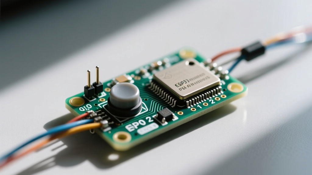
Unlike the classic Arduino Uno, where you can wire a mechanical pushbutton to almost any digital pin without consequence, the ESP32 architecture introduces a critical hardware constraint: strapping pins. During the boot sequence, the ESP32 samples specific GPIO pins to determine the boot mode, boot log output, and flash voltage. If your ESP32 button circuit forces a strapping pin into the wrong logic state during power-on, the microcontroller will fail to boot, enter UART download mode unexpectedly, or suffer a continuous brownout reboot loop.
Before wiring any switch to your ESP32 dev board, you must consult the strapping pin requirements. According to the Espressif GPIO API Reference, GPIO 12 is particularly dangerous for button circuits. If GPIO 12 is pulled HIGH during boot, the ESP32 attempts to set the internal flash voltage (VDD_SDIO) to 1.8V instead of the standard 3.3V, which will instantly crash most standard dev boards.
Safe vs. Unsafe GPIOs for Button Wiring
| GPIO Pin | Boot State Requirement | Safe for Active-Low Button? | Safe for Active-High Button? |
|---|---|---|---|
| GPIO 0 | HIGH (Normal Boot) / LOW (Flash) | No (Triggers Flash Mode) | Yes (Safe) |
| GPIO 2 | LOW or Floating (Normal Boot) | Yes (Safe) | No (Blocks Boot) |
| GPIO 12 | LOW (3.3V Flash) / HIGH (1.8V) | Yes (Safe) | No (Causes Brownout) |
| GPIO 15 | HIGH (Boot Log) / LOW (Silent) | No (Silences Logs) | Yes (Safe) |
| GPIO 32-39 | None (Safe ADC/Input Pins) | Yes (Highly Recommended) | Yes (Highly Recommended) |
Pro-Tip: For foolproof hardware design, always default to using GPIO 32, 33, 34, or 35 for your primary ESP32 button inputs. Note that GPIO 34-39 are input-only and lack internal pull-up resistors, requiring external 10kΩ resistors.
Hardware Configurations: Active-Low vs. Active-High
When designing the physical circuit for an ESP32 button, you must choose between an active-low or active-high configuration. This decision dictates whether the microcontroller reads a 0 or a 1 when the button is pressed.
The Gold Standard: Active-Low with Internal Pull-Ups
The most reliable and common method is the active-low configuration. You wire one side of the tactile switch to the GPIO pin and the other side directly to GND. By enabling the ESP32's internal pull-up resistor in software (INPUT_PULLUP), the pin rests at 3.3V (HIGH) and drops to 0V (LOW) when pressed.
The ESP32's internal pull-up resistors are approximately 45kΩ. While this is sufficient for short, controlled environments, the 45kΩ impedance is relatively weak. If your button is located more than 30cm away from the dev board via a ribbon cable, it will act as an antenna, picking up electromagnetic interference (EMI) and causing ghost presses. In noisy industrial or automotive environments, bypass the internal resistor and add an external 4.7kΩ to 10kΩ pull-up resistor tied directly to the 3.3V rail.
Why Active-High is Risky on the ESP32
In an active-high configuration, the button connects the GPIO to 3.3V when pressed, and an internal pull-down resistor (INPUT_PULLDOWN) keeps it at 0V when released. While the ESP32 does support internal pull-downs (also ~45kΩ), this configuration is generally discouraged because a disconnected or broken wire will float the pin, leading to erratic behavior, whereas a broken wire in an active-low setup simply defaults to a safe, unpressed HIGH state.
Software Polling and the Bounce2 Library
Mechanical switches suffer from contact bounce. When the metal contacts close, they physically vibrate, causing the ESP32 to read dozens of rapid HIGH/LOW transitions within a 1 to 5-millisecond window. If you use a simple if (digitalRead(buttonPin) == LOW) check inside your loop(), a single press might increment your counter by 15.
While you can write a custom millis() based debounce timer, the industry standard for Arduino and ESP32 environments is the Bounce2 Library on GitHub. It handles the state-change tracking and timing mathematics efficiently without blocking the main thread.
#include <Bounce2.h>

const int BUTTON_PIN = 32;
Bounce debouncer = Bounce();

void setup() {
  Serial.begin(115200);
  pinMode(BUTTON_PIN, INPUT_PULLUP);
  debouncer.attach(BUTTON_PIN);
  debouncer.interval(25); // 25ms debounce window
}

void loop() {
  debouncer.update();

  // Detect the exact moment the button is pressed (falling edge)
  if (debouncer.fell()) {
    Serial.println("Button Pressed!");
  }
}
This polling method is excellent for simple UI navigation or mode switching. However, if your loop() contains heavy tasks like driving WS2812B LED matrices or performing complex Wi-Fi MQTT parsing, the ESP32 might skip the 25ms window where the button is pressed, resulting in missed inputs. For mission-critical inputs, you must upgrade to hardware interrupts.
Advanced ISR: Dual-Core Interrupts and Spinlocks
The ESP32 is a dual-core microcontroller running FreeRTOS. When you use attachInterrupt(), the Interrupt Service Routine (ISR) can fire on either Core 0 or Core 1. If your main Arduino loop() is running on Core 1, but a network task on Core 0 attempts to read the button state variable modified by the ISR, you will encounter a race condition that can lead to memory corruption or a hard crash.
To write a truly robust ESP32 button ISR, you must use the IRAM_ATTR attribute to place the function in fast RAM, and implement a spinlock (portMUX_TYPE) to protect shared variables across both cores.
const int INTERRUPT_PIN = 33;
volatile int pressCount = 0;
portMUX_TYPE mux = portMUX_INITIALIZER_UNLOCKED;

void IRAM_ATTR buttonISR() {
  // Acquire spinlock to protect shared memory across dual cores
  portENTER_CRITICAL_ISR(&mux);
  pressCount++;
  portEXIT_CRITICAL_ISR(&mux);
}

void setup() {
  Serial.begin(115200);
  pinMode(INTERRUPT_PIN, INPUT_PULLUP);
  attachInterrupt(digitalPinToInterrupt(INTERRUPT_PIN), buttonISR, FALLING);
}

void loop() {
  int localCount;

  // Safely read the volatile variable using the same spinlock
  portENTER_CRITICAL(&mux);
  localCount = pressCount;
  portEXIT_CRITICAL(&mux);

  Serial.print("Total Presses: ");
  Serial.println(localCount);
  delay(500);
}
Hardware Debounce Warning for ISRs: Unlike software polling, an ISR will fire on every single microsecond of contact bounce. If you use the ISR code above without a hardware RC filter (a 100nF capacitor in parallel with the switch), your pressCount will skyrocket. Always pair hardware ISRs with a physical capacitor or a dedicated Schmitt trigger IC like the 74HC14.
The Buttonless Alternative: Capacitive Touch Pins
If you are designing a custom PCB and want to eliminate mechanical failure points entirely, the ESP32 features built-in capacitive touch sensing on 10 specific GPIO pins (e.g., GPIO 4, 12, 13, 14, 15, 27, 32, 33). By routing a copper pour on your PCB connected to one of these pins, you can detect the capacitance of a human finger through a plastic enclosure.
Using the touchRead() function, you can establish a baseline threshold. However, be aware that capacitive touch is highly susceptible to environmental humidity and requires careful software calibration to prevent false triggers when the ambient temperature shifts. For harsh industrial environments, stick to sealed mechanical switches on safe GPIOs; for sleek consumer IoT devices, capacitive touch offers a premium, waterproof user interface.