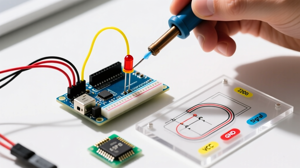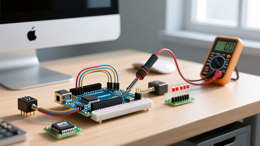

Unboxing the Arduino Starter Kit is a rite of passage for millions of makers, students, and engineers. Whether you are working with the official Rev 3 kit (retailing around $105 in 2026) or a third-party alternative like the Elegoo Super Starter (typically $35), the included 15 projects provide a fantastic foundation in embedded systems. However, the leap from software simulation to physical hardware is fraught with hidden traps. A misplaced jumper wire, a charge-only USB cable, or a misunderstood power rail can halt your progress entirely.
This comprehensive troubleshooting guide bypasses generic advice and dives deep into the exact failure modes, edge cases, and diagnostic steps required to fix the most common hardware and software errors encountered when building with the Arduino Starter Kit.
1. The 'Port Grayed Out' and Upload Failed Syndrome
The most frequent roadblock for beginners is the Arduino IDE refusing to recognize the board. In Arduino IDE 2.3.x, this manifests as a grayed-out port selection menu or an avrdude: ser_open(): can't open device error during compilation.
Identify Your USB-to-Serial Chip
The fix depends entirely on which version of the kit you own. The USB-to-serial converter chip on the Uno board dictates the driver requirements:
- Official Arduino Kits: Use the ATmega16U2 chip. These natively enumerate on Windows, macOS, and Linux without extra drivers. If it fails, the issue is almost always physical (cable or hub).
- Third-Party/Clone Kits: Use the CH340G or CH340C chip. These require a specific driver package to create a virtual COM port.
Step-by-Step Fix Protocol
- Eliminate Charge-Only Cables: Over 60% of 'dead board' reports stem from using a USB cable that lacks internal data lines (D+ and D-). Swap to a verified data cable, preferably the one included in the kit or a high-quality USB 2.0 A-to-B cable.
- Bypass USB Hubs: The ATmega328P microcontroller requires a stable 5V/500mA envelope during the bootloader handshake. Unpowered USB hubs often cause voltage sag, resetting the board mid-upload. Plug directly into the motherboard's rear I/O.
- Install CH340 Drivers (Clones Only): Download the latest signed CH340 driver from the manufacturer (WCH). On macOS 14+, ensure you grant the kernel extension permission in System Settings > Privacy & Security.
Expert Diagnostic Tip: If the port remains grayed out, double-click the reset button on the Uno board rapidly. This forces the ATmega16U2 into the bootloader's DFU (Device Firmware Upgrade) mode. If a new COM port briefly appears, your hardware is healthy, and the issue lies in your sketch monopolizing the serial buffer.
For deeper IDE-level debugging, consult the official Arduino Support documentation on grayed-out ports to parse verbose upload logs.
2. The Split Power Rail Trap (Breadboard Wiring)
Project 4 (Color Mixing Lamp) and Project 8 (Digital Hourglass) require extensive use of the breadboard's power rails. A notorious feature of the half-size (400-point) and full-size (830-point) breadboards included in most starter kits is the split power rail.
The Failure Mode
Look closely at the red and blue lines running horizontally along the edges of the breadboard. On many models, there is a physical gap in the metal spring clips right in the middle (usually around row 30). If you plug your 5V and GND into the top half, the bottom half of the board remains completely unpowered, leading to floating logic pins and erratic sensor readings.
The Fix
Use a multimeter set to continuity testing mode to verify your power distribution. Place one probe on the top-left 5V rail and the other on the bottom-right 5V rail. If the multimeter does not beep, bridge the center gap with a short jumper wire to unify the voltage rails across the entire board. For a complete primer on breadboard internal topology, review the SparkFun breadboard tutorial.
3. Servo Motor Jitter and Brownout Resets
When you reach the projects involving the SG90 micro servo (like the motorized potentiometer), you may notice the servo twitching violently, accompanied by the Uno's 'L' LED flashing or the board randomly restarting.
The Root Cause: USB Current Limits
The SG90 servo is rated for 4.8V to 6.0V. While its idle current is a mere ~10mA, its stall current (when the motor is under physical load or starting up) can spike to 700mA or higher. A standard USB 2.0 port is hardware-limited to 500mA. When the servo demands 700mA, the Uno's onboard 5V linear regulator and the host PC's USB protection circuitry experience a severe voltage drop (brownout). The ATmega328P's brown-out detection (BOD) triggers at 2.7V, instantly resetting the microcontroller.
Hardware Solutions
- The Capacitor Buffer (Quick Fix): Solder or plug a 470µF to 1000µF electrolytic capacitor directly across the servo's VCC (red) and GND (brown) wires. This provides a localized energy reservoir to handle the millisecond current spikes without dragging down the main USB voltage.
- External Power Supply (Proper Fix): Power the servo's red wire from an external 5V/2A buck converter or a dedicated battery pack. Crucial: You must tie the external power supply's GND to the Arduino's GND to establish a common reference voltage for the PWM control signal.
4. Floating Analog Values (Photoresistor & Potentiometer)
In Project 6 (Light Theremin), beginners often wire the GL5528 photoresistor (LDR) directly between 5V and Analog Pin A0, only to find the Serial Plotter displaying chaotic, random noise when the room is dark.
Understanding the Voltage Divider
An analog input pin measures voltage (0-5V), not resistance. The GL5528 has a dark resistance of ~1MΩ and a light resistance of ~10kΩ. Without a path to ground, the pin is 'floating' and acts as an antenna, picking up 50/60Hz mains hum from your environment.
The Exact Wiring Fix
You must create a voltage divider. Wire the circuit as follows:
- Connect 5V to one leg of the LDR.
- Connect the other leg of the LDR to Analog Pin A0 and to one leg of a 10kΩ pull-down resistor (included in the kit's resistor assortment).
- Connect the other leg of the 10kΩ resistor to GND.
This configuration ensures that when the LDR's resistance drops in bright light, the voltage at A0 approaches 5V (reading ~1023). In the dark, the 10kΩ resistor pulls the voltage down to near 0V (reading ~0), providing a stable, predictable analog range.
Diagnostic Matrix: Quick Reference Table
Use this matrix to rapidly isolate your issue based on the physical symptoms observed on your workbench.
| Symptom | Probable Root Cause | Exact Diagnostic Fix |
|---|---|---|
| IDE says 'Board at COMX not found' | CH340 driver missing or bad cable | Install WCH CH340 driver; swap to verified data cable. |
| Code uploads, but nothing happens | Sketch stuck in infinite while-loop or serial wait | Press physical RESET button; check for missing Serial.begin(). |
| LEDs are dim / flickering | Missing current-limiting resistor or short circuit | Verify 220Ω or 330Ω resistors are in series with all LEDs. |
| Sensor reads 1023 constantly | Short to 5V or missing pull-down resistor | Check breadboard for bridged solder/jumper; add 10kΩ to GND. |
| Uno gets physically hot to touch | Reverse polarity or >5V applied to 5V pin | Disconnect immediately. Check if 9V was mistakenly plugged into the '5V' header pin instead of the 'Vin' or barrel jack. |
Advanced Debugging: Enabling Verbose Output in IDE 2.x
When hardware checks pass but compilation or uploading still fails, the Arduino IDE's default error messages are often too vague. To expose the underlying avrdude or gcc compiler errors:
- Open File > Preferences (or Arduino IDE > Settings on macOS).
- Check the boxes for 'Show verbose output during: compilation' and 'upload'.
- Set the 'Compiler warnings' dropdown to 'All'.
- Re-run the upload. Scroll to the very bottom of the black console window. Look for specific memory overflow errors (e.g.,
region 'text' overflowed by X bytes), which indicate your sketch is too large for the Uno's 32KB flash memory, requiring you to optimize your code or move constant strings to flash memory using theF()macro.
Summary
Mastering the Arduino Starter Kit is less about memorizing code and more about developing a systematic approach to hardware debugging. By verifying your USB data lines, respecting the physical limitations of breadboard power rails, managing servo current spikes, and properly biasing analog sensors, you will eliminate 95% of the frustrations that cause beginners to abandon their projects. Keep your multimeter handy, trust the continuity beep, and always verify your ground connections.