
Learning how to control a fan with Arduino is a foundational skill for thermal management in custom enclosures, 3D printers, and DIY electronics projects. However, a common beginner mistake is attempting to wire a 12V PC fan directly to the microcontroller's I/O pins. The ATmega328P chip on an Arduino Uno or Nano has an absolute maximum DC current limit of 40mA per pin (with a recommended operating limit of 20mA). A standard 120mm 12V brushless DC fan, such as the Arctic P12 or Noctua NF-P12, draws between 100mA and 250mA at startup. Direct connection will instantly destroy your microcontroller.
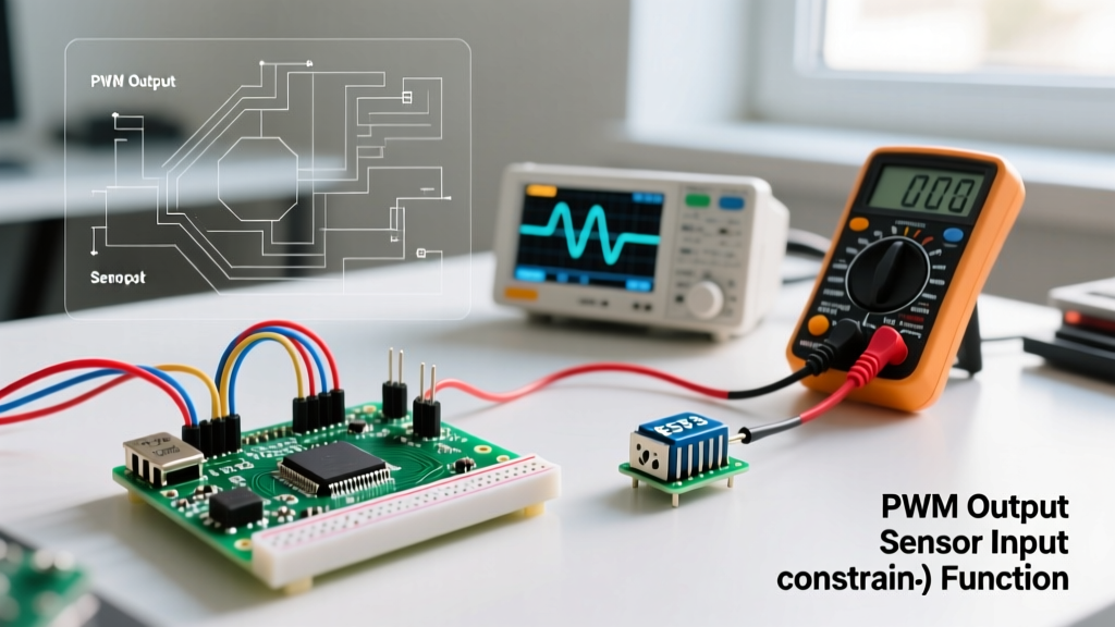
To safely bridge the gap between 5V logic and 12V power, we use a logic-level N-channel MOSFET as a low-side switch, combined with Pulse Width Modulation (PWM) to dictate fan speed. This guide details the exact circuit topology, component selection, and edge-case troubleshooting required for a robust 2026 build.
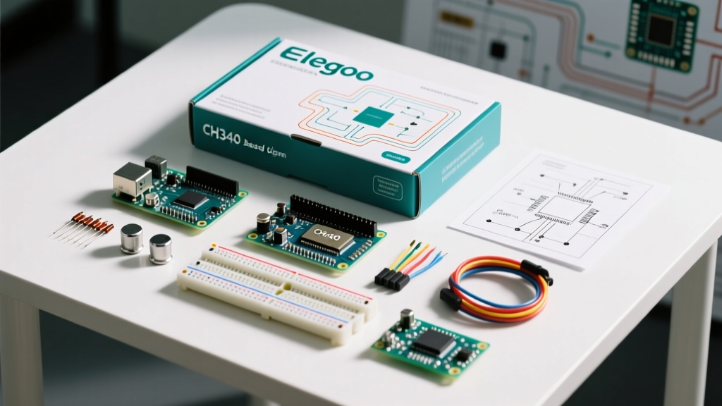
Bill of Materials and Component Specifications
Selecting the correct switching component is critical. While a standard BJT like the 2N2222 can handle the current, it suffers from a high voltage drop and requires continuous base current, generating excess heat. A logic-level MOSFET is vastly superior.
| Component | Specification / Model | Role in Circuit | Est. Cost (2026) |
|---|---|---|---|
| Microcontroller | Arduino Nano (ATmega328P) | PWM Signal Generation | $5.50 |
| Transistor | IRLZ44N N-Channel MOSFET | Power Switching (Logic-Level) | $1.20 |
| Diode | 1N4007 Rectifier | Flyback / Back-EMF Protection | $0.10 |
| Resistor | 10kΩ 1/4W Carbon Film | Gate Pull-Down | $0.05 |
| Fan | 120mm 12V DC Brushless | Cooling Load | $9.00 |
| Power Supply | 12V 2A DC Wall Adapter | Fan Power Rail | $8.00 |
Expert Note on the IRLZ44N: The 'L' in IRLZ44N stands for 'Logic-Level'. Standard MOSFETs like the IRF520 require 10V at the gate to fully turn on ($V_{GS}$). The IRLZ44N is fully enhanced at 5V, matching the Arduino's logic output perfectly, ensuring an ultra-low $R_{DS(on)}$ of roughly 22mΩ and virtually zero heat dissipation at fan currents.
Step-by-Step Hardware Wiring Guide
Proper wiring ensures signal integrity and protects your components from inductive voltage spikes. Follow this exact topology:
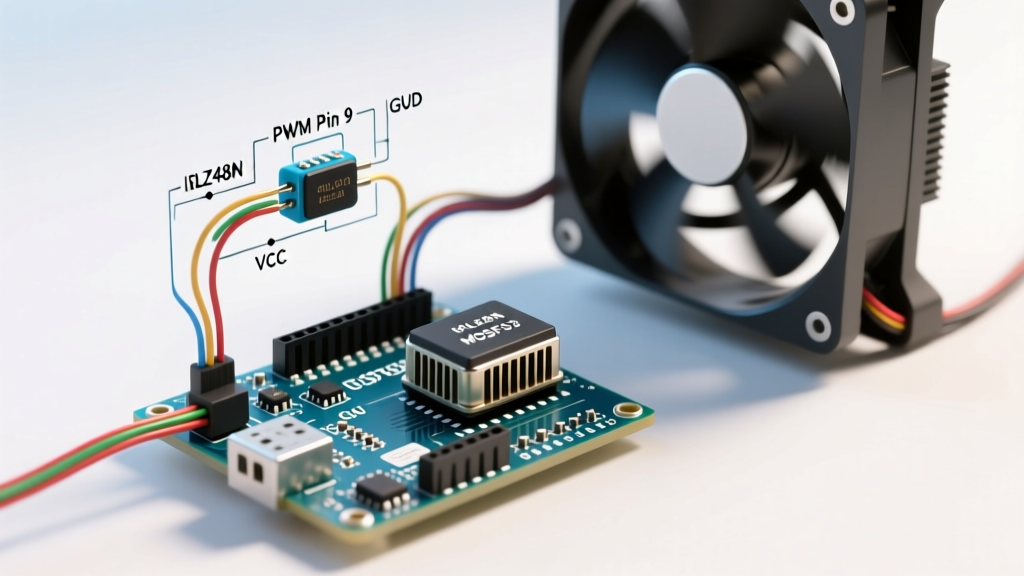
- Gate Connection: Connect Arduino Pin D3 (a PWM-capable pin) to the Gate of the IRLZ44N.
- Pull-Down Resistor: Connect a 10kΩ resistor between the Gate and Source (Ground). This prevents the gate from floating during the Arduino bootloader phase, which would otherwise cause the fan to spin erratically on startup.
- Source Connection: Connect the Source of the MOSFET to the common Ground.
- Drain Connection: Connect the Drain to the negative (black) wire of the 12V fan.
- Fan Power: Connect the positive (red or yellow) wire of the fan directly to the 12V Power Supply.
- Common Ground (Crucial): Connect the Ground of the 12V Power Supply to the Arduino Ground. Without a shared ground reference, the PWM signal cannot switch the MOSFET.
- Flyback Diode: Place a 1N4007 diode in reverse bias across the fan terminals (cathode/stripe to 12V positive, anode to Drain). Brushless motors contain inductive coils; when the MOSFET switches off, the collapsing magnetic field generates a reverse voltage spike (Back-EMF). The flyback diode safely recirculates this current, protecting the MOSFET from avalanche breakdown.
The Arduino Sketch: Mapping Analog Input to PWM
For this tutorial, we will use a 10kΩ potentiometer wired to Analog Pin A0 to manually dictate fan speed. The Arduino analogWrite() function handles the hardware-level PWM generation on Pin D3.
// Pin definitions
const int potPin = A0;  // Potentiometer wiper
const int fanPin = 3;   // Must be PWM capable (marked with ~)

void setup() {
  pinMode(fanPin, OUTPUT);
  Serial.begin(9600);

  // Optional: Kickstart the fan to overcome static friction
  analogWrite(fanPin, 255);
  delay(100);
}

void loop() {
  int potValue = analogRead(potPin); // Reads 0 to 1023

  // Map 0-1023 to 0-255 for PWM duty cycle
  int pwmValue = map(potValue, 0, 1023, 0, 255);

  // Apply a minimum threshold to prevent stalling
  if (pwmValue > 0 && pwmValue < 60) {
    pwmValue = 60; // Roughly 25% duty cycle minimum for 12V fans
  }

  analogWrite(fanPin, pwmValue);

  Serial.print("Pot: "); Serial.print(potValue);
  Serial.print(" | PWM: "); Serial.println(pwmValue);

  delay(50); // Debounce and smooth the signal
}
The 'Kickstart' and 'Stall' Thresholds
Notice the implementation of a 100ms pulse at 100% duty cycle in the setup() loop, and the minimum threshold of 60 in the loop(). 12V DC fans require a higher initial torque to overcome the static friction of the fluid dynamic bearings. If you apply a low PWM value (e.g., 30) from a dead stop, the fan will hum but fail to spin. The kickstart routine solves this, while the minimum threshold prevents the fan from stalling when the user dials the potentiometer too low.
Advanced Edge Case: 4-Wire PWM Fans and Acoustic Whine
If you are using a modern 4-wire PWM fan (commonly found in PC builds, featuring a dedicated blue PWM control wire), you will encounter a severe acoustic issue if you use the standard circuit above.
By default, the Arduino Uno/Nano generates PWM signals on Pins D3 and D11 at approximately 490 Hz. When a 4-wire fan's internal controller receives a 490 Hz signal, it translates this into a high-pitched, audible whining noise due to piezoelectric effects in the ceramic capacitors inside the fan hub. PC motherboards output PWM at 25 kHz, which is above the threshold of human hearing.
Fixing the PWM Frequency
To eliminate the whine when controlling 4-wire fans, you must manipulate the ATmega328P hardware timers to increase the PWM frequency to 31.25 kHz. Add this line to your setup() function:
void setup() {
  pinMode(fanPin, OUTPUT);
  // Set Timer 2 (Pins 3 & 11) to 31.25 kHz PWM
  TCCR2B = (TCCR2B & 0xF8) | 0x02;
}
Note: Altering Timer 2 will break the delay() and millis() functions if your sketch relies on them, as they share Timer 0. If you need precise timing alongside 25kHz PWM, use a dedicated hardware PWM IC like the PCA9685 or switch to an ESP32, which allows independent timer configuration via the LEDC peripheral.
Troubleshooting Matrix: Edge Cases and Failures
When building custom thermal controllers, environmental and electrical variables often cause unexpected behavior. Use this matrix to diagnose issues.
| Symptom | Probable Cause | Engineer's Fix |
|---|---|---|
| Fan spins at 100% immediately on power-up, ignores code. | Floating Gate during bootloader phase. | Verify the 10kΩ pull-down resistor is correctly bridging Gate and Source. |
| Fan stutters, hums, but does not spin at low speeds. | Insufficient starting torque / PWM too low. | Implement the software 'kickstart' routine and raise the minimum PWM floor to ~60. |
| MOSFET becomes too hot to touch. | Using a standard MOSFET (e.g., IRF520) instead of logic-level. | Replace with IRLZ44N. Standard MOSFETs operate in the linear (high-resistance) region at 5V logic. |
| Arduino resets randomly when fan turns off. | Back-EMF voltage spike coupling into the 5V rail. | Ensure the 1N4007 flyback diode is oriented correctly (stripe to 12V) and add a 100µF decoupling capacitor across the Arduino's 5V and GND pins. |
| Fan speed does not change; stays at one speed. | Using a non-PWM pin on the Arduino. | Move the Gate signal to a pin marked with a tilde (~), such as D3, D5, D6, D9, D10, or D11. |
By respecting the electrical characteristics of inductive loads and utilizing proper logic-level switching, you can build a highly reliable, silent, and efficient thermal management system. Whether you are cooling a high-power LED array, an enclosed Raspberry Pi cluster, or a custom 3D printer electronics bay, this MOSFET topology remains the gold standard for DC fan control.