
Introduction to CYD Hardware Quirks
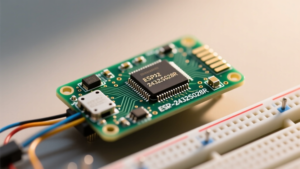
The ESP32-2432S028R, universally beloved in the maker community as the "Cheap Yellow Display" (CYD), pairs an ESP32-WROOM-32 module with a 2.8-inch ILI9341 TFT LCD and an XPT2046 touch controller. While countless esp32 development board esp32-2432s028r tutorials exist online, the vast majority gloss over the intricate hardware realities of this specific PCB layout. When makers copy-paste code from generic ESP32 guides, they inevitably hit a wall of undocumented errors: white screens, inverted touch matrices, bootloader timeouts, and random brownout reboots.
This comprehensive error diagnosis guide moves beyond basic "Hello World" sketches. We will dissect the exact failure modes of the ESP32-2432S028R, analyze the root causes of SPI bus contention, and provide hardware-level troubleshooting frameworks to get your project running reliably.
The "White Screen of Death": TFT_eSPI Configuration Failures
The most frequent point of failure when following esp32 development board esp32-2432s028r tutorials is the dreaded white screen. The backlight turns on (indicating GPIO 21 is receiving power), but the display remains blank. This is almost always a failure in the TFT_eSPI library configuration, specifically within the User_Setup.h file.
Diagnosing the Pin Matrix and Strapping Pin Conflicts
The CYD routes the ILI9341 display to the VSPI bus, but it uses GPIO 12 for TFT_MISO. On the ESP32, GPIO 12 is a critical strapping pin that determines the flash voltage (3.3V vs 1.8V) during boot. If the display pulls this pin high during the boot sequence, the ESP32 may enter an invalid boot mode or fail to initialize the SPI flash correctly.
Serial Monitor Error:
rst:0x10 (RTCWDT_RTC_RESET),boot:0x13 (SPI_FAST_FLASH_BOOT)
If you see this loop alongside a white screen, GPIO 12 is likely floating high.
The Fix: Ensure your User_Setup.h explicitly defines the correct CYD pinout. Do not rely on default generic ESP32 defines. Use the following exact mappings:
#define ILI9341_DRIVER#define TFT_MISO 12#define TFT_MOSI 13#define TFT_SCLK 14#define TFT_CS 15#define TFT_DC 2#define TFT_RST -1(Connected to the EN/Reset circuit)#define TFT_BL 21
Touch Matrix Inversion and XPT2046 SPI Bus Contention
The XPT2046 touch controller shares the same SPI bus as the ILI9341 display. A massive oversight in many beginner tutorials is failing to manage the Chip Select (CS) lines properly, leading to a completely unresponsive touch layer or wildly inaccurate coordinate mapping.
Resolving Touch CS and Interrupt Conflicts
The touch controller CS is hardwired to GPIO 33. If you do not define #define TOUCH_CS 33 in your User_Setup.h, the TFT_eSPI library will not initialize the touch SPI channel, and tft.getTouch() will perpetually return false.
Furthermore, the CYD routes the touch interrupt (IRQ) to GPIO 36. Because GPIO 36 is an input-only pin with no internal pull-up resistors, floating IRQ lines can cause massive CPU overhead if interrupts are enabled in software without external pull-ups. Diagnostic Tip: If your ESP32 is lagging or dropping WiFi packets while polling the touch screen, disable the hardware interrupt in your code and rely on a 5ms polling loop using tft.getTouch() instead.
Calibrating the Inverted Matrix
Depending on the specific manufacturing batch of the ESP32-2432S028R, the X and Y axes may be inverted or mirrored. Run the Touch_calibrate example sketch included in the TFT_eSPI library. This will output a calibration matrix to the Serial Monitor. Copy the resulting hex values directly into your setup() function using uint16_t calData[5] = { ... }; and apply it via tft.setTouch(calData);.
SD Card Mount Failures on the Shared SPI Bus
The CYD features a MicroSD card slot, but it is not connected to a dedicated SDIO bus; it shares the main SPI bus with the screen and touch controller. The SD Card CS pin is GPIO 5.
When tutorials attempt to initialize the SD card using the default SD.begin(), it fails silently. This happens because the default Arduino SD library attempts to use the HSPI bus and standard SPI clock speeds, which clash with the active display bus.
The Diagnostic Fix: You must explicitly pass the correct CS pin, the active SPI class, and a lowered clock speed to ensure bus stability:
if (!SD.begin(5, SPI, 1000000)) { Serial.println("SD Mount Failed"); }
Lowering the SPI frequency to 1MHz (1000000 Hz) during initialization prevents signal reflection issues on the relatively long, unshielded PCB traces of the CYD.
Bootloader Timeouts and CH340 Driver Diagnostics
A fatal error in the Arduino IDE stating Failed to connect to ESP32: Timed out waiting for packet header is a rite of passage. This is rarely a broken board; it is a strapping pin and driver issue.
The GPIO 0 Boot Sequence
To enter the UART download bootloader, GPIO 0 must be pulled LOW at the exact moment the ESP32 resets. The CYD has a tactile button labeled "BOOT" connected to GPIO 0. Diagnostic Workflow: Press and hold the BOOT button. Tap the "RST" (Reset) button. Release the BOOT button. Only then click "Upload" in the Arduino IDE. For automated uploading, ensure your USB cable is fully wired (data + power) and not a charge-only cable.
Additionally, the CYD utilizes the CH340C USB-to-UART bridge, not the CP2102 found on premium DevKits. Ensure you have installed the official WCH CH340 drivers for your OS, as generic Windows drivers often drop the DTR (Data Terminal Ready) signal required to automatically trigger the GPIO 0 boot sequence.
Hardware-Level Power Delivery and Brownout Faults
Perhaps the most insidious error encountered in advanced esp32 development board esp32-2432s028r tutorials is the random reboot under load. The CYD regulates USB 5V down to 3.3V using an AMS1117-3.3 LDO. This linear regulator is highly inefficient and prone to thermal throttling.
Diagnosing the Brownout Detector (BOD)
If you enable the TFT backlight to 100% duty cycle (GPIO 21 HIGH), turn on the RGB LED, and initiate a heavy WiFi transmission (like an HTTP GET request or MQTT publish), the instantaneous current draw can exceed 400mA. The AMS1117 will experience severe voltage droop, dropping the 3.3V rail below 2.8V. The ESP32's internal Brownout Detector will instantly trigger a reset.
Serial Monitor Output:
Brownout detector was triggered
Solutions:
- Software Mitigation: Never run the backlight at 100%. Use PWM on GPIO 21 and cap the duty cycle at 70%.
- WiFi Power Saving: Call
WiFi.setSleep(WIFI_PS_MIN_MODEM);to reduce peak TX current spikes. - Hardware Modification: For demanding projects, bypass the onboard AMS1117 entirely by feeding a regulated, high-quality 3.3V source directly into the 3V3 pin on the breakout headers, bypassing the USB power path.
Quick-Reference Diagnostic Matrix
Use this table to rapidly isolate faults when your build deviates from standard tutorial expectations.
| Symptom | Probable Root Cause | Diagnostic Step | Hardware/Software Fix |
|---|---|---|---|
| White Screen, Backlight ON | Incorrect TFT_eSPI Pin Mapping | Verify User_Setup.h defines |
Set TFT_CS 15, TFT_DC 2, ILI9341_DRIVER |
| Touch Unresponsive | Missing Touch CS Definition | Check Serial debug for XPT2046 init | Add #define TOUCH_CS 33 |
| SD Card Fails to Mount | SPI Bus Contention / Speed | Test with 1MHz SPI clock | Use SD.begin(5, SPI, 1000000) |
| Random Reboots under Load | AMS1117 Voltage Droop (BOD) | Monitor 3.3V rail with oscilloscope | Limit Backlight PWM, external 3.3V LDO |
| Upload Timeout | GPIO 0 Strapping / CH340 DTR | Check Serial Monitor boot flags | Manual BOOT+RST sequence, update CH340 drivers |
Conclusion
Mastering the ESP32-2432S028R requires looking past the surface-level code provided in generic guides. By understanding the shared SPI architecture, the quirks of the ESP32 strapping pins, and the thermal limits of the onboard voltage regulator, you can transform this budget-friendly hardware into a robust platform for industrial IoT dashboards, smart home controllers, and portable diagnostic tools. Always consult the definitive CYD hardware documentation and Espressif bootloader guidelines when pushing the board to its limits.