
The Hidden Workflow Bottlenecks of the DHT11
The DHT11 is arguably the most ubiquitous temperature and humidity sensor in the maker ecosystem. At a bare-bones price point of $1.20 to $1.80 per unit, it is the default choice for introductory environmental monitoring. However, as projects scale from simple serial-monitor printouts to complex, multi-threaded IoT deployments in 2026, the DHT11 frequently transforms from a cheap convenience into a severe workflow bottleneck.
The primary issue is not the sensor itself, but how the standard DHT11 Arduino integration is traditionally handled. Most legacy tutorials rely on blocking delays and ignore the strict microsecond-level timing requirements of the sensor's custom single-bus protocol. This leads to a cascade of workflow interruptions: failed compilations, NaN (Not a Number) readings, checksum errors, and frozen main loops. This guide focuses entirely on workflow optimization—streamlining your hardware configuration, implementing non-blocking software architectures, and eliminating the edge cases that waste hours of bench time.
Hardware Workflow: Wiring for Zero-Failure Reads
The most common point of failure in a DHT11 Arduino setup occurs before a single line of code is compiled. The DHT11 utilizes a proprietary 1-wire communication protocol that requires precise voltage transitions. If your physical layer is compromised, no software library can save your workflow.
The Pull-Up Resistor Miscalculation
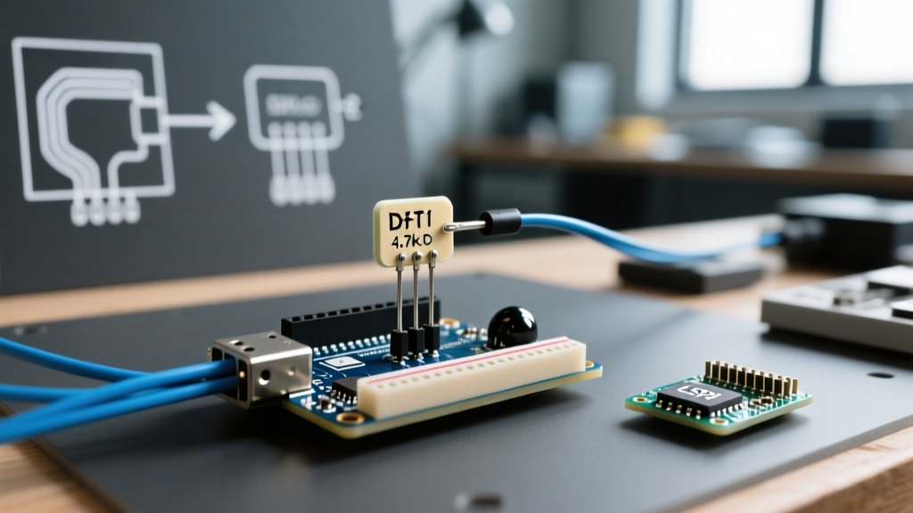
The standard DHT11 module (the blue 4-pin PCB version with a $2.50 retail price) includes a 10kΩ surface-mount pull-up resistor. If you are using the bare 4-pin blue plastic component (approx. $1.20), you must supply your own pull-up. While 10kΩ works on a breadboard with 10cm jumper wires, it fails catastrophically in real-world enclosures where wire runs exceed 50cm due to parasitic capacitance.
Workflow Pro-Tip: Never rely on the Arduino's internal INPUT_PULLUP (approx. 20kΩ-50kΩ) for the DHT11 data line. The internal pull-up is too weak to pull the bus high fast enough to meet the sensor's 20-40 microsecond rise-time requirements, guaranteeing checksum errors.
To optimize your hardware workflow and eliminate intermittent timeout errors, match your external pull-up resistor to your wire length:
| Wire Length (Data Pin to Sensor) | Recommended Pull-Up Resistor | Expected Bus Capacitance |
|---|---|---|
| < 25 cm (Breadboard) | 4.7kΩ (Standard) | < 15 pF |
| 25 cm - 1 Meter | 2.2kΩ | 15 pF - 50 pF |
| 1 Meter - 3 Meters | 1kΩ | 50 pF - 150 pF |
| > 3 Meters | Not Recommended (Use I2C Sensor) | > 150 pF |
Software Workflow: Killing the Blocking Delay
The traditional workflow for reading a DHT11 involves calling dht.readHumidity() and dht.readTemperature(), which internally triggers a blocking delay of up to 250 milliseconds to 2 seconds, depending on the library. In a modern 2026 workflow utilizing ESP32 dual-core processing or RP2040 multicore architectures, blocking the main thread to wait for a $1.50 sensor is unacceptable. It starves WiFi stacks, drops MQTT packets, and causes watchdog timer (WDT) resets.
Implementing a Non-Blocking State Machine
To optimize your software workflow, you must decouple the sensor's mandatory 1-second sampling rate from your microcontroller's main loop. The DHT11 requires a minimum of 1 second between reads to allow its internal thermistor and capacitive humidity element to stabilize.
Instead of using delay(1000), implement a millis() based state machine. This ensures your Arduino or MCU remains fully responsive to button presses, network events, and display refreshes.
- Initialize Timestamp: Create an
unsigned long lastDHTRead = 0;variable. - Check Interval: In the
loop(), evaluateif (millis() - lastDHTRead >= 2000). (Using 2 seconds provides a safety buffer against the sensor's internal timing drift). - Execute & Update: Trigger the read function, validate the output for NaN, and immediately update
lastDHTRead = millis();.
For comprehensive timing reference, always consult the official Arduino Millis Documentation to ensure you are handling unsigned long rollover correctly—a common bug that crashes long-running environmental monitors after 49 days.
Decoding Failure Modes: Checksum vs. Timeout Errors
When your serial monitor spits out errors, knowing exactly what they mean saves hours of blind troubleshooting. According to the Components101 DHT11 Datasheet, the sensor transmits 40 bits of data (16-bit humidity, 16-bit temperature, 8-bit checksum).
1. Timeout Errors (Start Signal Failure)
The Cause: The Arduino pulls the data line LOW for 18ms to wake the sensor, then HIGH for 40us. The sensor should respond by pulling LOW for 80us. If the Arduino doesn't see this 80us pulse, it throws a Timeout.
The Fix: This is almost always a wiring or power issue. Verify the sensor is receiving a stable 5V (or 3.3V for specific logic-level shifted variants). Ensure your ground wire is not sharing a return path with high-current components like motors or relays, which can cause ground bounce and mask the start pulse.
2. Checksum Errors (Data Corruption)
The Cause: The sensor sent the 40 bits, but the sum of the first four bytes did not match the fifth byte. This means bits were dropped or stretched during transmission.
The Fix: This is a timing or capacitance issue. If you are using an ESP8266 or ESP32, background WiFi interrupts can stretch the microsecond timing loops of the DHT library. Optimize your workflow by using libraries specifically designed to disable interrupts during the 4ms read window, or migrate to an I2C-based sensor if WiFi latency is unavoidable.
Environmental Edge Cases and Thermal Bleed
A frequently overlooked workflow killer is thermal contamination. The DHT11's internal thermistor is highly susceptible to heat radiating from nearby components. If you mount a DHT11 less than 3cm away from an AMS1117 voltage regulator, an L298N motor driver, or even the onboard regulator of an Arduino Uno, your temperature readings will artificially inflate by 2°C to 4°C.
Optimization Strategy: Always design your PCB or perfboard layout with the DHT11 at the extreme edge of the board, with ventilation slots milled into the enclosure directly adjacent to the sensor mesh. For enclosed deployments, use a passive draft tube or a small 5V brushless fan (approx. $3.00) to pull ambient air over the sensor.
Sensor Migration Matrix: When to Upgrade Your Workflow
Part of workflow optimization is knowing when a component is no longer fit for purpose. While the DHT11 is fine for basic prototyping, professional deployments require higher resolution and faster I2C bus integration. Use the matrix below to decide when to pivot your hardware workflow.
| Sensor Model | Protocol | Temp Resolution | Avg. Cost (2026) | Best Use Case |
|---|---|---|---|---|
| DHT11 | Custom 1-Wire | 1.0°C | $1.50 | Basic education, simple data logging |
| DHT22 (AM2302) | Custom 1-Wire | 0.1°C | $4.50 | Wider temp ranges (-40 to 80°C) |
| AHT20 | I2C | 0.01°C | $2.80 | Compact IoT nodes, non-blocking reads |
| Sensirion SHT31-D | I2C | 0.01°C | $6.50 | High-precision, industrial, harsh environments |
Conclusion: Streamlining the DHT11 Arduino Experience
Optimizing your DHT11 Arduino workflow is not about writing faster code; it is about respecting the physical and electrical limitations of the hardware. By upgrading your pull-up resistors for longer wire runs, abandoning blocking delays in favor of millis() state machines, and strategically placing the sensor away from thermal noise, you can transform the DHT11 from a frustrating debugging hurdle into a reliable, set-and-forget environmental monitor. For further reading on sensor integration and wiring best practices, the Adafruit DHT Sensor Guide remains an excellent foundational resource for understanding the underlying 1-wire timing mechanics.