
The 2026 Standard for RGB LED Light Arduino Projects
Building a custom lighting rig or interactive art piece often starts with a simple premise: wire up an rgb led light arduino circuit and write a few lines of code. However, as projects scale from a single indicator to a multi-node array, makers inevitably hit a wall of spaghetti wiring, muddy color mixing, and camera-visible PWM flicker. In 2026, the most successful hardware prototypers do not rely on ad-hoc trial and error; they use a structured, optimized workflow.
This guide details a professional-grade workflow for standard 4-pin RGB LEDs, focusing on hardware budgeting, physical connection standards, HSV color space architecture, and high-frequency PWM manipulation to eliminate flicker.
Phase 1: Component Selection and Power Budgeting
The foundation of an optimized workflow is selecting components with predictable forward voltages (Vf) and establishing a strict power budget. The industry-standard workhorse for through-hole prototyping is the Kingbright WP154A4SURKQBDZGW (5mm common cathode, water-clear lens). Priced at roughly $0.45 per unit in bulk, it offers excellent luminosity but requires precise current limiting to prevent thermal runaway and color shifting.
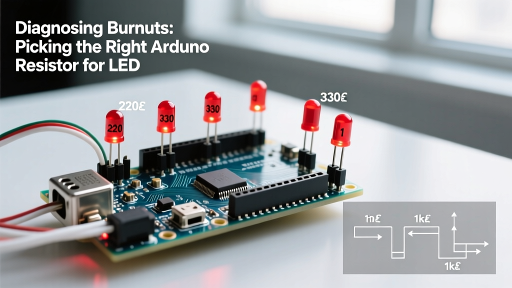
Calculating Exact Current Limiting Resistors
Never use a single resistor on the common cathode/aneode pin. As different color channels are toggled, the total current changes, altering the voltage drop and causing the colors to shift dynamically. You must use three independent resistors.
- Red Channel (Vf = 2.0V): Target 20mA. R = (5V - 2.0V) / 0.02A = 150Ω.
- Green Channel (Vf = 3.2V): Target 20mA. R = (5V - 3.2V) / 0.02A = 90Ω (Use 91Ω 1% precision).
- Blue Channel (Vf = 3.2V): Target 20mA. R = (5V - 3.2V) / 0.02A = 90Ω (Use 91Ω 1% precision).
Pro-Tip: If you are driving more than 15 RGB LEDs simultaneously, abandon the Arduino’s onboard 5V regulator. Inject power directly from a dedicated 5V 10A switching power supply (like the Mean Well LRS-50-5) to prevent brownouts and microcontroller resets.
Phase 2: Standardizing the Physical Workflow
Breadboards are the enemy of optical consistency. The internal spring contacts introduce variable resistance (often 0.5Ω to 2Ω per node), which subtly alters voltage delivery and ruins precise color calibration across multiple LEDs.
The JST-XH Rapid Prototyping Method
To optimize your physical build process, transition to a modular wiring harness using JST-XH 2.54mm pitch connectors. A 100-piece kit costs around $12 and completely transforms your assembly speed.
- Solder the LED Array: Solder your RGB LEDs and their specific resistors onto a piece of perfboard or a custom rapid-PCB.
- Crimp the Harness: Crimp a 4-pin JST-XH connector to the LED array (Pins: Red, Green, Blue, Common).
- Standardize Wire Colors: Adopt a strict color code. Red wire for Red channel, Green for Green, Blue for Blue, and Black for Common Cathode (or White for Common Anode).
- Plug and Play: Mate the harness to a corresponding header on your Arduino shield or custom breakout board. This allows you to swap faulty LEDs in seconds without desoldering.
For deeper insights on managing power injection and physical wiring best practices, the Adafruit NeoPixel ÜberGuide Best Practices remains an invaluable resource, as the principles of voltage drop and wire gauge sizing apply equally to standard analog RGB arrays.
Phase 3: Software Architecture (Ditching Raw RGB)
The most common bottleneck in an rgb led light arduino workflow is attempting to mix colors using raw Red, Green, and Blue values (0-255). Human vision does not perceive light linearly, and the RGB color space is highly unintuitive for creating smooth transitions or specific hues like “warm amber” or “deep magenta.”
Adopting HSV and Gamma Correction
Optimize your code by shifting to the HSV (Hue, Saturation, Value) color space. Hue (0-360) represents the color wheel, Saturation (0-255) represents the intensity of the color, and Value (0-255) represents brightness. You can leverage the math libraries built into the FastLED ecosystem, even if you are driving standard analog LEDs via PWM. As documented in the FastLED Color Spaces Wiki, converting HSV to RGB mathematically ensures perfect hue transitions without the “muddy” gray dead-zones inherent in manual RGB mixing.
Implementing a Gamma Lookup Table (LUT)
Because the human eye is more sensitive to changes in dark tones than bright tones, a PWM value of 127 (50% duty cycle) appears roughly 75% as bright as 255. To fix this, implement a 256-byte Gamma Correction LUT in your Arduino’s PROGMEM. This maps your linear software inputs to the non-linear PWM outputs required for smooth, perceptually uniform dimming.
Phase 4: Eliminating PWM Flicker for Video
By default, the Arduino Uno’s analogWrite() function operates at approximately 490 Hz (or 980 Hz on pins 5 and 6). While this is fast enough for the human eye, it creates severe banding and flickering when recorded by smartphone cameras or DSLRs operating at standard shutter speeds. To optimize your project for video capture or photography, you must increase the PWM frequency to at least 20 kHz.
Manipulating Timer1 Registers
Pins 9 and 10 on the ATmega328P are controlled by Timer1. By modifying the Timer/Counter Control Registers (TCCR1A and TCCR1B) in your setup() function, you can push the frequency to ~20 kHz. This is a critical workflow step for any installation meant to be filmed. For a foundational understanding of how these timers dictate pin behavior, refer to the official Arduino PWM Tutorial.
Workflow Comparison Matrix: Ad-Hoc vs. Optimized
| Workflow Stage | Ad-Hoc / Beginner Approach | Optimized 2026 Workflow |
|---|---|---|
| Current Limiting | Single resistor on common pin | 3x independent precision resistors |
| Wiring | Direct breadboard jumper wires | Soldered perfboard with JST-XH harnesses |
| Color Mixing | Manual RGB guessing (0-255) | HSV math via FastLED + Gamma LUT |
| PWM Frequency | Default 490 Hz (Camera flicker) | Timer1 manipulated to 20 kHz |
| Power Delivery | Arduino 5V pin (Max 500mA) | Dedicated 5V PSU with common ground |
Edge Cases and Failure Modes
Even with an optimized workflow, specific edge cases can derail your rgb led light arduino project. Keep this troubleshooting checklist handy:
- Ghosting / Faint Glow on “Off” Channels: Often caused by induced voltage from adjacent wires in long harnesses. Fix: Add 10kΩ pull-down resistors from each PWM pin to ground to bleed off stray capacitance.
- Color Shifting at Low Brightness: Occurs when using standard RGB math without Gamma correction. Fix: Apply the Gamma LUT mentioned in Phase 3 before writing to the PWM pins.
- Microcontroller Brownouts: Happens when all LEDs flash white (maximum current draw) simultaneously, dropping the 5V rail below 4.5V. Fix: Inject a 1000µF electrolytic capacitor across the main power rails near the LED array to buffer transient current spikes.
- Ground Loop Noise: If using an external PSU for the LEDs but powering the Arduino via USB, differing ground potentials can cause erratic PWM behavior. Fix: Ensure a thick (18 AWG or larger) common ground wire connects the Arduino GND pin directly to the PSU’s negative terminal.
Conclusion
Transitioning from a hobbyist mindset to an engineered workflow transforms the rgb led light arduino experience from a frustrating exercise in debugging to a reliable, scalable process. By standardizing your hardware with precision resistors and JST connectors, adopting HSV color spaces with gamma correction, and manipulating hardware timers to eliminate flicker, you ensure your lighting projects are robust, visually stunning, and ready for professional deployment.