
Understanding the DS18B20 1-Wire Protocol
The DS18B20 digital temperature sensor remains a staple in environmental monitoring, DIY weather stations, and industrial prototyping. Unlike analog thermistors that require complex Steinhart-Hart equation calculations and are susceptible to voltage reference drift, the DS18B20 outputs a fully calibrated, digital 1-Wire signal. When pairing the DS18B20 and Arduino microcontrollers, makers gain access to a highly accurate (±0.5°C from -10°C to +85°C) sensor that requires only a single digital GPIO pin for communication.
Originally designed by Dallas Semiconductor and now manufactured by Analog Devices (following their acquisition of Maxim Integrated), the DS18B20 utilizes the proprietary 1-Wire bus protocol. This protocol embeds both power delivery and bidirectional data transmission over a single wire, provided the circuit is configured correctly. In this comprehensive configuration guide, we will dissect the hardware wiring topologies, bus capacitance limitations, and software library configurations required to achieve rock-solid temperature readings in 2026.
Hardware Pinout and Electrical Specifications
Before soldering or breadboarding, it is critical to understand the electrical boundaries of the sensor. The DS18B20 operates on a supply voltage (VDD) ranging from 3.0V to 5.5V, making it natively compatible with both 5V Arduino Uno/Nano boards and 3.3V ESP32/Arduino Due architectures.
| Parameter | Specification | Design Note |
|---|---|---|
| Supply Voltage (VDD) | 3.0V to 5.5V | Tolerant of standard 3.3V and 5V logic levels. |
| Standby Current | 1.0 µA (max) | Ideal for battery-powered, deep-sleep IoT nodes. |
| Active Conversion Current | 1.5 mA (max) | Crucial for sizing parasitic power pull-up resistors. |
| Temperature Range | -55°C to +125°C | Accuracy degrades to ±2°C outside the -10°C to +85°C band. |
| Default Resolution | 12-bit (0.0625°C) | Configurable via EEPROM to 9, 10, 11, or 12 bits. |
For the ubiquitous waterproof stainless-steel probe variant, the wiring color code is almost universally standardized across manufacturers: Red for VDD (Power), Black for GND (Ground), and Yellow (or sometimes White) for DQ (Data). Always verify this with a multimeter if you are sourcing unbranded probes from overseas marketplaces, as miswiring VDD and GND will instantly destroy the internal ASIC.
Critical Wiring Configurations: Normal vs. Parasitic Power
The most common point of failure when integrating the DS18B20 and Arduino is misunderstanding the power delivery modes. The sensor supports two distinct hardware configurations: External Power Mode (Normal) and Parasitic Power Mode.
1. External Power Mode (Recommended for Most Projects)
In this mode, the sensor draws power directly from the Arduino's 5V or 3.3V rail. This is the most stable configuration and is highly recommended for multi-drop buses (multiple sensors on one pin) or long cable runs.
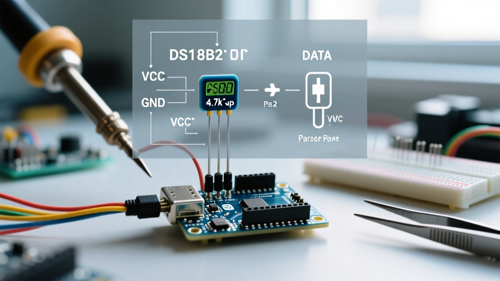
- VDD (Red): Connect to Arduino 5V or 3.3V.
- GND (Black): Connect to Arduino GND.
- DQ (Yellow): Connect to Arduino Digital Pin 2.
- Pull-up Resistor: A 4.7kΩ resistor must be placed between the DQ line and the VDD rail.
2. Parasitic Power Mode (For 2-Wire Cable Constraints)
Parasitic power allows the sensor to harvest energy directly from the data line, storing it in an internal capacitor during the high logic state. This mode requires only two physical wires (Data and Ground) to reach the sensor, which is useful when retrofitting existing 2-wire alarm or telephone cabling.
- VDD (Red): Connect directly to GND (Pin 3 must be grounded in parasitic mode).
- GND (Black): Connect to Arduino GND.
- DQ (Yellow): Connect to Arduino Digital Pin 2.
- Pull-up Resistor: A 4.7kΩ resistor is standard, but see the 'Advanced Troubleshooting' section below regarding current limits.
Expert Warning: During a 12-bit temperature conversion, the DS18B20 draws up to 1.5 mA of current. A standard 4.7kΩ pull-up resistor connected to 5V can only source roughly 1.06 mA (Ohm's Law: 5V / 4700Ω). If using Parasitic Power Mode, you must use a stronger pull-up (e.g., 2.2kΩ) or an active MOSFET-based pull-up circuit to prevent the data line from browning out mid-conversion, which yields the infamous85°Cor-127°Cerror codes.
Scaling Up: The Multi-Drop 1-Wire Bus
One of the greatest advantages of the 1-Wire protocol is the ability to daisy-chain dozens of sensors on a single Arduino GPIO pin. Every DS18B20 has a unique, factory-lasered 64-bit ROM serial number embedded in its silicon. However, adding sensors increases the bus capacitance, which degrades the signal rise time.
If you are wiring more than three sensors, or if your cable runs exceed 5 meters, you must adjust your pull-up resistor. According to the Analog Devices DS18B20 Datasheet, as bus capacitance increases, the pull-up resistance must decrease to maintain the required microsecond-level timing edges.
| Number of Sensors / Cable Length | Recommended Pull-Up Resistor | Expected Bus Capacitance |
|---|---|---|
| 1-3 sensors / < 3 meters | 4.7 kΩ | < 150 pF |
| 4-10 sensors / 3 to 10 meters | 2.2 kΩ | 150 pF - 400 pF |
| > 10 sensors / > 10 meters | 1.0 kΩ or Active Pull-Up | > 400 pF |
Software Configuration and Library Setup
To interface the DS18B20 and Arduino at the firmware level, you must bypass standard digital read/write functions and use strict timing-based bit-banging. Fortunately, the open-source community has abstracted this into two highly reliable libraries.
Required Libraries
- OneWire Library: Originally written by Jim Studt and currently maintained by Paul Stoffregen. This handles the low-level 1-Wire timing, ROM searching, and CRC8 validation. You can review the protocol specifics on the PJRC OneWire Reference Page.
- DallasTemperature Library: Maintained by Miles Burton, this library sits on top of OneWire and provides high-level functions like
requestTemperatures()andgetTempCByIndex().
Finding Your Sensor's 64-Bit Address
While you can read sensors by their index (e.g., Sensor 0, Sensor 1), this is dangerous in production environments. If a sensor fails or is disconnected, the indices of the remaining sensors will shift, causing your Arduino to log incorrect data to the wrong variables. Always hardcode the 64-bit ROM address into your sketch.
Upload the OneWireSearch example sketch included with the OneWire library. Open the Serial Monitor at 115200 baud. The output will provide a hexadecimal array that looks like this:
ROM = 28 FF 64 1D 86 16 03 2A
Copy this array into your main sketch to create a dedicated DeviceAddress variable. This guarantees that 'Probe A' always maps to 'Probe A', regardless of the physical order in which the Arduino discovers them on the bus during boot.
Advanced Configuration: Resolution and Conversion Timing
A frequently overlooked configuration parameter is the ADC resolution. Out of the box, the DS18B20 defaults to 12-bit resolution. While this provides a granular 0.0625°C step size, it requires a maximum conversion time of 750 milliseconds. In battery-powered applications where the Arduino wakes from deep sleep, takes a reading, and transmits via LoRa or Wi-Fi, waiting 750ms per sensor burns valuable mAh.
| Resolution (Bits) | Temperature Step Size | Max Conversion Time | Use Case |
|---|---|---|---|
| 9-bit | 0.5°C | 93.75 ms | Fast HVAC room monitoring, low-power sleep nodes. |
| 10-bit | 0.25°C | 187.5 ms | General purpose ambient weather stations. |
| 11-bit | 0.125°C | 375 ms | Incubators, terrariums requiring tighter control loops. |
| 12-bit (Default) | 0.0625°C | 750 ms | Laboratory calibration, thermal profiling of PCBs. |
You can change the resolution dynamically in your code using the setResolution(address, 9) function. To make this change permanent across power cycles, you must follow it with the saveScratchPad() command, which writes the configuration block to the sensor's internal EEPROM. Note that the EEPROM is rated for roughly 50,000 write cycles, so only execute the save command once during setup, not inside your main loop.
Troubleshooting Edge Cases and Signal Degradation
Even with perfect wiring, environmental factors and code mismanagement can cause erratic behavior. Here is how to diagnose the most common DS18B20 and Arduino failure modes:
The '85°C' Power-On Default Error
If your serial monitor reads exactly 85.00°C, the sensor has not performed a conversion. The DS18B20's scratchpad defaults to 85°C on startup. This error occurs when your code requests the temperature before the 750ms conversion window has elapsed, or if the parasitic power line sagged during the conversion phase, resetting the sensor's internal state machine. Fix: Ensure you are using sensors.setWaitForConversion(true) or manually delaying your code, and verify your pull-up resistor is supplying adequate current.
The '-127°C' Disconnect Error
A reading of -127°C (or sometimes -196°F) indicates that the Arduino's OneWire library failed the CRC8 checksum validation or could not find the device on the bus. Fix: This is almost always a physical layer issue. Check for cold solder joints, broken wires inside the waterproof probe's heat-shrink collar, or a missing pull-up resistor. If using long cables, ensure you are not routing the 1-Wire data cable parallel to AC mains or high-current DC lines, as electromagnetic interference (EMI) will corrupt the microsecond-level 1-Wire timing pulses.
Ghosting and Bus Contention
If you see random, wildly fluctuating temperatures across multiple sensors, you may be experiencing bus contention. This happens when two sensors attempt to pull the bus low simultaneously during the ROM search phase. Ensure that your wiring topology is a linear 'daisy-chain' or a 'star' with very short stubs. Avoid creating long, unterminated branching loops in your 1-Wire cabling, as signal reflections will cause the Arduino to misinterpret bit states.
By respecting the electrical boundaries of the 1-Wire protocol, sizing your pull-up resistors according to bus capacitance, and hardcoding your 64-bit ROM addresses, your DS18B20 and Arduino integration will deliver years of reliable, maintenance-free thermal data.