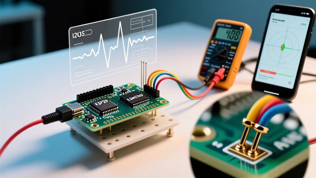

The Anatomy of AHRS Arduino Failures
Building an Attitude and Heading Reference System (AHRS) with an Arduino is a rite of passage for robotics and drone makers. By fusing data from a 3-axis gyroscope, accelerometer, and magnetometer (a 9-DOF IMU), you can calculate precise 3D orientation. However, moving from a breadboard prototype to a functional AHRS Arduino deployment often exposes harsh realities: magnetic interference, I2C bus lockups, and sensor fusion timing jitter.
In 2026, while legacy chips like the MPU9250 are largely phased out due to rampant counterfeiting, modern alternatives like the TDK ICM-20948 and Bosch BNO086 dominate. Yet, the fundamental physics and communication protocols remain the same. This guide provides deep-dive error diagnosis for the most common AHRS Arduino failures, moving beyond basic wiring tutorials into actual hardware and software debugging.
Diagnosing Yaw Drift: Hard vs. Soft Iron Distortion
Pitch and roll are generally stable because they rely on the accelerometer's reference to Earth's gravity (1G). Yaw, however, relies entirely on the magnetometer referencing Earth's magnetic field. If your AHRS yaw drifts, snaps back to a wrong heading, or behaves erratically when rotated, you are experiencing magnetic distortion.
Identifying the Signature
- Hard Iron Distortion: Caused by permanent magnets or ferrous metals near the sensor (e.g., steel chassis, nearby speakers). This adds a constant offset vector to the magnetic readings. Symptom: The plotted magnetometer data forms a sphere, but its center is shifted away from the origin (0,0,0).
- Soft Iron Distortion: Caused by materials that alter the ambient magnetic field (e.g., copper PCB traces, aluminum enclosures, or nearby current-carrying traces). Symptom: The plotted data forms an ellipsoid (stretched or skewed sphere) rather than a perfect sphere.
The Calibration Protocol
If you are using a chip with an onboard fusion engine like the Bosch BNO055, you must monitor the calibration status registers. According to the Adafruit BNO055 documentation, the sensor outputs calibration scores from 0 to 3 for the System, Gyro, Accelerometer, and Magnetometer. Your AHRS is invalid until the Magnetometer and System registers hit 3.
To achieve this, you must perform a continuous figure-8 motion in 3D space. If you are in an indoor environment with steel rebar or HVAC ducting, the local magnetic field may be too warped to achieve a '3' rating. In these hostile magnetic environments, you must disable the magnetometer in your fusion algorithm and rely on a 6-DOF (Gyro + Accel) setup, accepting that yaw will drift over time unless corrected by an external reference like GPS or optical encoders.
I2C Bus Lockups: When the Arduino Freezes
The most catastrophic error in an AHRS Arduino project is the I2C bus lockup. Your code is running perfectly, and suddenly the microcontroller freezes entirely. The `Wire.endTransmission()` function hangs indefinitely, and the watchdog timer (if not configured correctly) fails to reset the board.
The 5V vs 3.3V Logic Trap: Most modern 9-DOF IMUs (like the ICM-20948) operate at 3.3V logic. Connecting them directly to a 5V Arduino Uno or Mega without a logic level shifter (like the BSS138) will slowly degrade the IMU's internal I2C pull-up resistors, eventually causing the SDA line to latch low.
Hardware Fixes: Pull-ups and Capacitance
The I2C protocol relies on open-drain lines. If your IMU breakout board lacks sufficient pull-up resistors, the signal edges will be too slow, causing the Arduino to misinterpret bits and lock up.
- 100kHz Bus: Use 4.7kΩ pull-up resistors to 3.3V on both SDA and SCL.
- 400kHz Bus: Use 2.2kΩ pull-up resistors to accommodate the faster rise times.
- Bus Capacitance: The I2C specification limits bus capacitance to 400pF. Long wires or multiple sensors on the same bus will exceed this, causing signal degradation. Keep I2C traces under 30cm.
Software Recovery: The 9-Clock Pulse Trick
If the Arduino resets while the IMU is transmitting a '0' bit, the IMU will hold the SDA line low, waiting for the master to provide a clock pulse. Because the Arduino just reset, it assumes the bus is free and tries to initiate a start condition, which fails because SDA is already low.
To fix this, implement an I2C bus recovery routine in your `setup()` function before calling `Wire.begin()`. Toggle the SCL pin as a standard GPIO output 9 times. This forces the slave IMU to finish its byte and release the SDA line. The official Arduino Wire communication guide touches on bus states, but implementing this manual SCL toggling is a mandatory industry practice for robust AHRS deployments.
Sensor Fusion Timing Jitter (Madgwick/Mahony Filters)
If you are using raw IMU data and calculating the AHRS on the Arduino using the Madgwick or Mahony filter algorithms, timing jitter will destroy your orientation output. As detailed in Sebastian Madgwick's original AHRS research, the filter requires a precise delta-time (`dt`) parameter to integrate the gyroscope's degrees-per-second into absolute degrees.
The `delay()` Anti-Pattern
Using `delay(10)` in your main loop is a fatal error. The actual loop execution time will be 10ms plus the time it takes to read the I2C registers (which can vary from 1ms to 4ms depending on bus traffic). This jitter causes the filter to over-integrate or under-integrate the gyro data, resulting in a creeping pitch/roll drift.
| Method | Jitter Profile | AHRS Suitability |
|---|---|---|
delay(10) |
High (1-5ms variance) | Unusable (Severe Drift) |
millis() polling |
Medium (1ms resolution) | Poor (Gyro integration errors) |
micros() delta |
Low (4µs resolution) | Excellent (Standard approach) |
| Hardware Timer Interrupt | None (Deterministic) | Professional (Required for drones) |
Tuning the Beta Parameter: In the Madgwick filter, the `beta` parameter dictates the trust balance between the gyroscope and the accelerometer. If your AHRS output is noisy and twitches during vibration, your `beta` is too high (trusting the noisy accelerometer). If the AHRS drifts slowly over time, `beta` is too low (trusting the drifting gyro). For most Arduino setups with standard vibration isolation, a `beta` value between 0.1 and 0.5 provides the optimal compromise.
2026 IMU Component Comparison Matrix
Selecting the right hardware prevents software headaches. Here is how the current market leaders compare for Arduino AHRS projects:
| IMU Model | Typical Price | Fusion Engine | Common Failure Mode | Best Use Case |
|---|---|---|---|---|
| Bosch BNO055 | ~$34.99 | Onboard (Hardware) | Calibration loss on power cycle | Robotics, indoor rovers |
| TDK ICM-20948 | ~$14.99 | DMP (Requires complex firmware loading) | I2C address conflicts, DMP firmware load failures | Wearables, lightweight drones |
| Bosch BNO086 | ~$29.99 | Onboard (Sensor Hub) | SPI/I2C mode pin misconfiguration | High-precision VR tracking, AGVs |
| MPU9250 (Clones) | ~$4.00 | None (Raw data only) | Counterfeit silicon, massive temperature drift | Not recommended for 2026 projects |
Summary Checklist for AHRS Deployment
- Isolate the Magnetometer: Mount the IMU at least 10cm away from motors, high-current ESC wires, and steel fasteners.
- Verify I2C Integrity: Check for 4.7kΩ pull-ups to 3.3V and implement the 9-pulse SCL recovery routine in your setup code.
- Eliminate Timing Jitter: Replace all `delay()` functions with `micros()` delta-time calculations or hardware interrupts.
- Save Calibration Data: If using a BNO055 or BNO086, write the calibration offsets to the Arduino's EEPROM or an SD card during startup to bypass the figure-8 calibration dance on every power cycle.
By addressing these physical and protocol-level bottlenecks, your AHRS Arduino project will transition from a fragile prototype to a robust, drift-free orientation system capable of handling real-world deployment.