
The Physics: Why an Arduino LED and Resistor Must Be Paired
When you first unbox an Arduino Uno R3 or R4, the temptation to plug a 5mm LED directly into the 5V and GND pins to test it is immense. Doing so will result in a brilliant, fleeting flash of light followed by the distinct smell of burning silicon. Understanding how to properly match an Arduino LED and resistor is the foundational step in embedded systems engineering. An LED (Light Emitting Diode) is a non-linear semiconductor device. Unlike a standard incandescent bulb, it does not have a fixed resistance. Once the voltage across the LED reaches its specific 'forward voltage' threshold, its internal resistance drops to near zero, causing current to spike exponentially.
Without a current-limiting resistor in series, the LED will attempt to draw infinite current from the Arduino's GPIO pin. This will instantly exceed the ATmega328P microcontroller's absolute maximum rating of 40mA per pin, permanently damaging the silicon die's internal bond wires. Furthermore, according to the official Arduino digital pins documentation, the total current sourced across all VCC/GND pins must not exceed 200mA to prevent package-wide thermal shutdown.
Step 1: Calculating the Correct Resistor Value
To safely interface an Arduino LED and resistor, we rely on Ohm's Law. The formula to find the required resistance ($R$) is:
R = (Vsource - Vforward) / Iforward
Where Vsource is the Arduino GPIO output voltage (typically 5V on a Uno, 3.3V on a Due or ESP32), Vforward (Vf) is the LED's forward voltage drop, and Iforward (If) is the desired current in Amperes.
Standard LED Forward Voltage Reference Table
Different semiconductor dopants create different colors and voltage drops. Below is a reference chart for standard 5mm through-hole LEDs, such as the widely available Lite-On LTL-307EE series:
| LED Color | Typical Vf (Volts) | Recommended If (mA) | Wavelength (nm) |
|---|---|---|---|
| Infrared (IR) | 1.2V - 1.5V | 20mA - 50mA | 850 - 940 |
| Red | 1.8V - 2.2V | 15mA - 20mA | 620 - 750 |
| Yellow / Orange | 2.0V - 2.2V | 15mA - 20mA | 590 - 620 |
| Pure Green | 3.0V - 3.2V | 20mA | 520 - 540 |
| Blue / White / UV | 3.0V - 3.5V | 20mA - 30mA | 450 - 480 (Blue) |
Real-World Calculation Example
Let's calculate the resistor for a standard Red LED on a 5V Arduino Uno pin. We will target a safe, bright current of 15mA (0.015A) to prolong the LED's lifespan and reduce strain on the microcontroller.
- Vsource = 5.0V
- Vforward = 2.0V (from datasheet)
- Iforward = 0.015A
R = (5.0 - 2.0) / 0.015 = 3.0 / 0.015 = 200Ω.
Since 200Ω is not a standard value in the common E12 resistor series, we round up to the nearest available value: 220Ω. Rounding up slightly reduces the current, which is always the safer engineering choice. A standard KOA Speer 1/4W (0.25W) metal film resistor costs roughly $0.02 in bulk and is perfectly rated for this. To verify, we calculate power dissipation: P = I² × R = (0.015)² × 220 = 0.0495W, well below the 0.25W limit.
Step 2: Hardware Wiring and Breadboard Setup
Proper physical wiring is just as critical as the math. LEDs are polarized components, meaning current must flow in only one direction. As detailed in the SparkFun LED tutorial, identifying the anode and cathode is mandatory.
- Identify the Anode (+): The longer leg of the 5mm LED is the anode. Internally, it connects to the smaller metal post.
- Identify the Cathode (-): The shorter leg is the cathode. The plastic lens casing will also have a flat notch on the side of the cathode.
- Insert the LED: Place the LED across the center trench of your solderless breadboard so the anode and cathode are in separate rows.
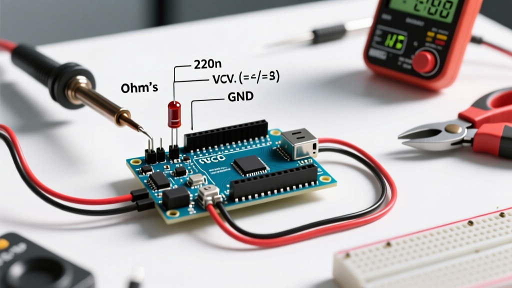
- Place the Resistor: Insert one leg of your 220Ω resistor into the same row as the LED's anode. Resistors are non-polarized, so orientation does not matter.
- Wire to Arduino: Use a male-to-male jumper wire to connect the free leg of the resistor to Digital Pin 8 on the Arduino. Use another jumper wire to connect the LED's cathode directly to any GND pin.
Step 3: Writing the Arduino Blink Sketch
With the hardware secured, we must configure the GPIO pin to source current. Open the Arduino IDE and upload the following optimized blink sketch:
// Define the pin connected to the resistor
const int LED_PIN = 8;

void setup() {
  // Configure the pin as an output to source current
  pinMode(LED_PIN, OUTPUT);
}

void loop() {
  digitalWrite(LED_PIN, HIGH); // Output 5V, turning the LED ON
  delay(500);                  // Wait 500 milliseconds
  digitalWrite(LED_PIN, LOW);  // Output 0V, turning the LED OFF
  delay(500);                  // Wait 500 milliseconds
}
Pro-Tip for 2026 Maker Projects: While delay() is fine for simple tutorials, it blocks the CPU. For advanced projects involving sensors or Wi-Fi (like the ESP32), replace delays with millis() based non-blocking timers to keep your main loop responsive.
Advanced Edge Cases and Failure Modes
Even with the correct Arduino LED and resistor pairing, real-world physics introduces edge cases that beginners often overlook.
1. Reverse Bias Avalanche Breakdown
What happens if you wire the LED backward? Unlike rectifier diodes that can withstand hundreds of volts in reverse, standard indicator LEDs have a very low reverse breakdown voltage, typically around 5V. If connected backward directly to a 5V pin, the LED will experience avalanche breakdown. While the internal resistance of the Arduino GPIO pin might save it from instant death, the semiconductor junction will degrade, leading to a permanent loss of luminosity over time.
2. The Internal Pull-Up Resistor Trap
The ATmega328P features internal pull-up resistors (typically 20kΩ to 50kΩ) that can be activated via pinMode(pin, INPUT_PULLUP). Some makers attempt to use these to light an LED without an external resistor. While a 20kΩ resistor will limit the current to roughly 0.15mA—preventing the chip from burning out—the LED will be so dim it is barely visible in a lit room. Always use dedicated external 1/4W resistors for illumination.
3. Sourcing vs. Sinking Current
The circuit described above uses 'current sourcing' (current flows from the GPIO pin, through the LED, to GND). Alternatively, you can use 'current sinking' (current flows from 5V, through the LED and resistor, into the GPIO pin set to LOW). According to the Microchip ATmega328P datasheet, the absolute maximum current for both sourcing and sinking is 40mA per pin. However, sinking is often preferred in LED matrix multiplexing because it aligns better with open-drain configurations and external driver ICs like the ULN2803.
Frequently Asked Questions
Can I wire multiple LEDs to a single Arduino pin?
Yes, but you must calculate the total current. If you wire three Red LEDs in parallel, each with its own 220Ω resistor, the pin will source roughly 45mA (15mA x 3). This exceeds the 40mA absolute maximum limit and will slowly degrade the GPIO pin. For multiple LEDs, wire them in series (requiring a higher voltage source) or use a logic-level MOSFET like the IRLZ44N to handle the heavy lifting.
Does the resistor go on the anode or cathode side?
Electrically, it does not matter. In a series circuit, the current is identical at all points. The resistor will limit the current equally whether it is placed between the GPIO pin and the anode, or between the cathode and GND. However, standard industry practice places the resistor on the anode (high side) for easier troubleshooting with a multimeter.
Do I need a resistor for the built-in Pin 13 LED?
No. On the Arduino Uno, the built-in 'L' LED connected to Pin 13 is already wired in series with a 1kΩ resistor and an op-amp buffer circuit on the PCB. You can safely toggle Pin 13 in your code without adding external components.