
Building a Reliable Tachometer for Arduino
Constructing a precise tachometer for Arduino requires more than simply attaching a sensor to a spinning shaft. Whether you are measuring the RPM of a brushless DC (BLDC) motor, a CNC spindle, or a custom wind turbine, signal noise, interrupt latency, and timing errors can easily ruin your telemetry. This quick reference guide answers the most frequent hardware and software questions encountered by makers and engineers when designing RPM measurement systems in 2026.
Sensor Selection Matrix
Choosing the right transducer is the first critical step. Below is a comparison of the three most common sensor modules used in Arduino tachometer projects, including current market pricing and operational limits.
| Sensor Type | Common Module / IC | Best Application | Max Reliable RPM | Typical Cost (2026) |
|---|---|---|---|---|
| Hall Effect | KY-003 / A3144 | BLDC motors, harsh environments, embedded magnets | 30,000 RPM | $1.20 - $2.50 |
| IR Optical | FC-03 / LM393 Comparator | Slotted optical disks, low-speed conveyors | 10,000 RPM | $1.00 - $1.80 |
| Quadrature Encoder | HEDS-5540 / CUI AMT103 | High-precision CNC, closed-loop servo control | 100,000+ RPM | $15.00 - $45.00 |
Hardware & Wiring FAQs
Q: Do I need external pull-up resistors for my Hall effect sensor?
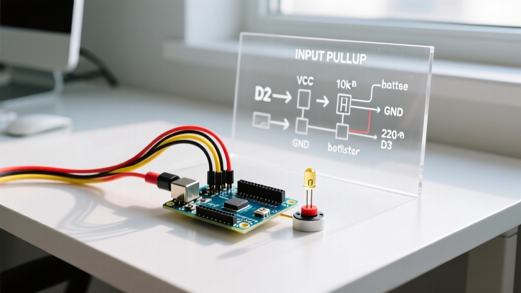
A: It depends on the module. If you are using a bare A3144 Hall effect IC, you absolutely need a 10kΩ pull-up resistor between the VCC (5V or 3.3V) and the signal output pin, as the A3144 features an open-collector output. However, if you are using the ubiquitous KY-003 breakout board, it already includes an onboard 10kΩ pull-up resistor and a power indicator LED. Supplying 5V to a KY-003 will yield a clean 5V digital HIGH, making it directly compatible with 5V Arduino boards like the Uno R3 or Mega 2560.
Q: How do I eliminate EMI noise from the motor I am measuring?
A: Electric motors—especially brushed DC motors and stepper drivers—generate massive electromagnetic interference (EMI) that can induce ghost pulses in your sensor cables. To harden your tachometer for Arduino against EMI:
- Twisted Pair Wiring: Always route your sensor signal and ground wires as a twisted pair to reject common-mode noise.
- Local Decoupling: Solder a 100nF (0.1µF) ceramic capacitor directly across the VCC and GND pins at the sensor head, not just at the Arduino end.
- Shielding: For high-noise environments, use a shielded cable and tie the shield to the Arduino's ground at one end only to prevent ground loops.
Expert Insight: Never run your 5V sensor signal wire parallel to the motor's PWM or power cables. If you must cross them, do so at a strict 90-degree angle to minimize inductive coupling.
Software & Calculation FAQs
Q: Why should I use micros() instead of millis() for RPM math?
A: Resolution and accuracy. Consider a shaft spinning at 10,000 RPM with one magnet attached. That equates to 166.6 Hz, meaning one pulse arrives every 6 milliseconds. If you use millis(), your timing resolution is 1ms. A 1ms jitter results in a massive 16% error margin in your RPM reading. By using micros(), which resolves to 4µs increments, your timing error drops to less than 0.1%. Always capture timestamps using micros() inside your Interrupt Service Routine (ISR).
Q: What is the most accurate formula to calculate RPM?
A: For instant, low-latency readings, measure the time elapsed between consecutive pulses rather than counting pulses over a fixed one-second window. The formula is:
RPM = 60000000 / (delta_micros * pulses_per_revolution)
Where delta_micros is the difference between the current and previous micros() timestamps. Note that pulses_per_revolution must account for magnetic pole pairs. A standard BLDC motor with 14 poles will generate 7 pulses per physical revolution, meaning your divisor must be adjusted accordingly.
Q: Do I really need to declare my timing variables as volatile?
A: Yes. Variables modified inside an ISR and read inside the main loop() must be declared as volatile. This instructs the AVR or ARM compiler to bypass CPU register caching and always fetch the variable directly from SRAM. Failing to do so will result in the main loop reading stale, cached data, causing your tachometer display to freeze or stutter. Furthermore, when reading a multi-byte volatile variable (like an unsigned long used by micros()) in the main loop, you must temporarily disable interrupts using noInterrupts() and interrupts() to prevent data tearing if an interrupt fires mid-read.
Troubleshooting Edge Cases
Issue: The RPM reads exactly double the actual speed.
Root Cause: You are likely triggering the interrupt on CHANGE instead of FALLING or RISING. Hall effect sensors pull the line LOW when a magnet approaches and release it HIGH when it leaves. Triggering on CHANGE counts both the approach and the departure.
Fix: Change your interrupt attachment to attachInterrupt(digitalPinToInterrupt(pin), ISR_Name, FALLING);. For deeper context on handling signal transitions and preventing false triggers, refer to the official Arduino attachInterrupt() documentation.
Issue: The Arduino freezes or stutters at high RPMs.
Root Cause: Your ISR is too 'heavy'. If you are performing floating-point math, updating an I2C OLED display, or printing to the Serial monitor directly inside the ISR, you will block the main program and potentially cause I2C bus timeouts. At 30,000 RPM, an interrupt fires every 2 milliseconds; an I2C transaction can easily take 1-2ms, causing a catastrophic collision.
Fix: Keep the ISR strictly limited to capturing the micros() timestamp and setting a boolean flag. Perform all RPM math and display updates in the main loop() based on that flag.
Issue: Erratic RPM spikes at low speeds.
Root Cause: Switch bounce or mechanical vibration causing the sensor to hover at the threshold voltage. While Hall sensors are less prone to mechanical bounce than physical switches, magnetic field distortion from shaft runout can cause 'chatter' at the threshold.
Fix: Implement software debouncing by ignoring any interrupt that fires within 500µs of the previous valid pulse. For a comprehensive guide on managing signal bounce and threshold chatter, review the All About Circuits guide on switch bounce and signal conditioning.
Display Integration Quick Reference
When outputting your tachometer data, avoid using Serial.print() in the main loop without a non-blocking timer. Serial transmission at 9600 baud takes roughly 1ms per character, which will introduce severe loop latency. Instead, use a 0.96-inch I2C OLED display (SSD1306 driver, I2C address 0x3C). Utilizing the U8g2 library allows for fast, buffered rendering. Update the display no faster than 10 Hz (every 100ms) to provide a stable, human-readable RPM readout without bogging down the microcontroller's I2C bus.
For makers integrating high-resolution quadrature encoders rather than simple single-pulse tachometers, managing the A/B phase states requires specialized state-machine logic. The SparkFun Rotary Encoder Hookup Guide provides excellent baseline schematics for decoding quadrature signals via hardware interrupts and pin-change interrupts on AVR-based boards.