
The Silent Failures of Arduino Wireless Communication
Deploying Arduino wireless communication modules in the field is where theoretical datasheets meet harsh electrical reality. While a breadboard prototype might transmit packets flawlessly across a desk, moving that same circuit into an enclosure or extending the range to 500 meters often introduces silent failures: corrupted payloads, unexplained microcontroller resets, and SPI bus lockups. In 2026, despite the availability of advanced SoCs like the ESP32-C6 (Wi-Fi 6) and Semtech SX1262 (LoRa), makers and engineers still rely heavily on legacy nRF24L01+ modules and older ESP32 variants for cost-sensitive telemetry.
This guide bypasses basic library installation tutorials and dives directly into the hardware-level edge cases, power delivery flaws, and timing mismatches that cause wireless communication errors. We will dissect the exact failure modes of 2.4GHz RF, Sub-GHz LoRa, and Wi-Fi modules, providing actionable oscilloscope-level diagnostics and code-level overrides.
Diagnostic Matrix: Symptom to Root Cause
Before desoldering components or rewriting your sketch, cross-reference your specific failure mode with this diagnostic matrix. Wireless errors are rarely random; they follow predictable electrical patterns.
| Symptom | Primary Suspect | Affected Modules | Quick Diagnostic Test |
|---|---|---|---|
| TX works on desk, fails at >5 meters | VCC sag during RF PA burst | nRF24L01+, HC-12, ESP32 | Scope VCC pin during TX; look for >150mV droop. |
| Radio fails to initialize (Serial prints 'failed') | SPI clock edge rounding / MISO float | nRF24L01+, SX1278, SX1262 | Reduce SPI clock to 2MHz; check CSN pull-up. |
| MCU randomly reboots during transmission | Brownout Detector (BOD) trip / Ground bounce | ESP32, ESP8266 | Disable BOD via code; measure GND pin vs USB shield. |
| Interrupts never fire (RX hangs) | Wrong DIO pin mapping / Non-interrupt pin | SX1278, SX1262, RFM95 | Verify DIO0/DIO1 maps to hardware INT (Uno: Pin 2/3). |
| MQTT timeouts / High latency spikes | Wi-Fi 6 TWT sleep states / Router mismatch | ESP32-C6, ESP32-S3 | Force 802.11n (Wi-Fi 4) PHY mode in code. |
Deep Dive 1: nRF24L01+ Power Starvation & SPI Race Conditions
The nRF24L01+ remains a staple for short-range mesh networks, but it is notorious for intermittent packet loss. The root cause is almost always tied to transient current demands and parasitic capacitance on the SPI bus.
The 3.3V Regulator Trap
When the nRF24L01+ enters TX mode at 0dBm, it draws roughly 11.3mA. However, if you are using a module with the onboard PA/LNA (Power Amplifier/Low Noise Amplifier) and an external antenna, the TX current spikes to 115mA for less than 2 milliseconds. Most cheap Arduino sensor shield adapters use a counterfeit or undersized AMS1117-3.3 LDO that cannot deliver this transient current without the output voltage sagging below the module's 1.9V minimum operating threshold, causing an internal state-machine reset.
The Fix: Do not rely on the Arduino's onboard 3.3V pin. Use a dedicated buck converter (like the LM2596-3.3) or add a local energy reservoir. Solder a 10µF Tantalum capacitor in parallel with a 100nF X7R MLCC directly across the VCC and GND pins on the module's PCB. The Tantalum handles the low-frequency burst envelope, while the MLCC shunts high-frequency switching noise. For a comprehensive hardware overview, refer to the SparkFun nRF24L01 Transceiver Hookup Guide.
SPI Bus Capacitance and Clock Speed
The popular TMRh20 RF24 Arduino library defaults to a 10MHz SPI clock speed. If you are using standard 20cm breadboard jumper wires, the parasitic capacitance (typically 15pF per cm) combined with the ATmega328P's output impedance rounds the sharp square-wave clock edges into sine waves. By the time the clock reaches the nRF24L01+, the module misinterprets the SPI commands, leading to initialization failures.
The Fix: Force the SPI clock down to 2MHz or 4MHz in your initialization code. In the RF24 library, modify the constructor:
// Default (often fails on long wires)
RF24 radio(7, 8);

// Fixed (forces 2MHz SPI clock)
RF24 radio(7, 8, 2000000);
Deep Dive 2: LoRa (SX1278 / SX1262) Antenna & Interrupt Mapping
Sub-GHz LoRa modules offer kilometer-range communication, but they are highly sensitive to RF mismatches and software-hardware mapping errors.
The Fatal "No Antenna" Mistake
Unlike Wi-Fi modules that can safely transmit into an open SMA connector, LoRa power amplifiers are highly sensitive to Voltage Standing Wave Ratio (VSWR). If you initiate a TX packet without a properly tuned antenna attached, the RF energy reflects back into the SX1278/SX1262 silicon, destroying the internal PA matching network in seconds. A replacement SX1262 module costs around $6.50 in 2026, but the downtime and debugging cost are high. Always use a 50-ohm dummy load if bench-testing without an antenna.
The DIO0 vs. DIO1 Interrupt Shift
A massive source of "RX hanging" errors in recent projects stems from the transition from the legacy SX1278 to the modern SX1262.
- SX1278: Uses the
DIO0pin to signal "TX Done" and "RX Done". - SX1262: Consolidates interrupts onto the
DIO1pin.
If you copy-paste a RadioHead or LoRa library example designed for an SX1278 onto an SX1262 board, the MCU will wait forever for an interrupt on a pin that the radio never toggles. Furthermore, ensure the pin you map to DIO1 on your Arduino Uno/Nano is a hardware interrupt pin (Pin 2 or Pin 3). Mapping it to Pin 11 (which is SPI MOSI) will cause catastrophic bus collisions.
Deep Dive 3: ESP32 Wi-Fi Stack Crashes & Brownouts
The ESP32 family dominates IoT, but its Wi-Fi stack is a resource hog. The most common error seen in the serial monitor is the dreaded: Brownout detector was triggered.
Power Supply Ripple and USB Cable Voltage Drop
When the ESP32 transmits a Wi-Fi beacon or an MQTT payload, the RF subsystem draws upwards of 240mA in a 5-millisecond burst. If you are powering the dev board via a standard USB-C cable with thin 28AWG internal wires, the cable resistance can exceed 0.8 ohms. Ohm's law dictates a voltage drop of nearly 0.2V just across the cable, which, combined with the onboard LDO dropout voltage, starves the 3.3V core, triggering the hardware Brownout Detector (BOD) and causing a panic reset.
The Fix:
1. Upgrade to a high-quality USB cable rated for 5A (which uses thicker 22AWG or 20AWG wires).
2. Bypass the onboard USB-to-UART LDO entirely by feeding a clean 5.05V directly into the 5V pin from an external LM2596 buck converter.
3. If operating in a high-noise industrial environment where power sags are unavoidable, you can lower the BOD threshold in your code (though this risks memory corruption if the voltage drops too low):
#include "soc/soc.h"
#include "soc/rtc_cntl_reg.h"

void setup() {
  // Disable Brownout Detector
  WRITE_PERI_REG(RTC_CNTL_BROWN_OUT_REG, 0);
  // Initialize Wi-Fi...
}
ESP32-C6 and Wi-Fi 6 Target Wake Time (TWT)
In 2026, the ESP32-C6 is widely adopted for its Wi-Fi 6 (802.11ax) support. Wi-Fi 6 introduces Target Wake Time (TWT), allowing the radio to sleep deeply between router-scheduled beacon intervals. While excellent for battery life, if your local router is an older Wi-Fi 5 model or has a buggy TWT implementation, the ESP32-C6 will experience massive latency spikes (2 to 5 seconds), causing strict MQTT keep-alive timeouts. If your application requires low-latency real-time control, force the ESP32-C6 into Wi-Fi 4 (802.11n) mode via the Espressif Wi-Fi API Guidelines:
WiFi.setPhyMode(WIFI_PHY_MODE_11N);Expert Tip: The Ground Plane Imperative
If your 2.4GHz or Sub-GHz module has a PCB trace antenna (like the meandering inverted-F antenna on ESP-12F or bare nRF24L01+ SMD chips), the antenna relies on the copper ground plane on the host PCB to act as the other half of the dipole. Mounting these modules on a breadboard or a wooden enclosure without a dedicated ground plane will detune the antenna, shifting the resonant frequency and dropping your range by up to 80%. Always design a contiguous ground pour directly beneath trace antennas.
Advanced Debugging: Logic Analyzer Workflow
When Serial prints fail, you must look at the raw wires. A $15 USB logic analyzer (like a Saleae Logic clone) running PulseView or Sigrok is mandatory for diagnosing SPI wireless errors.
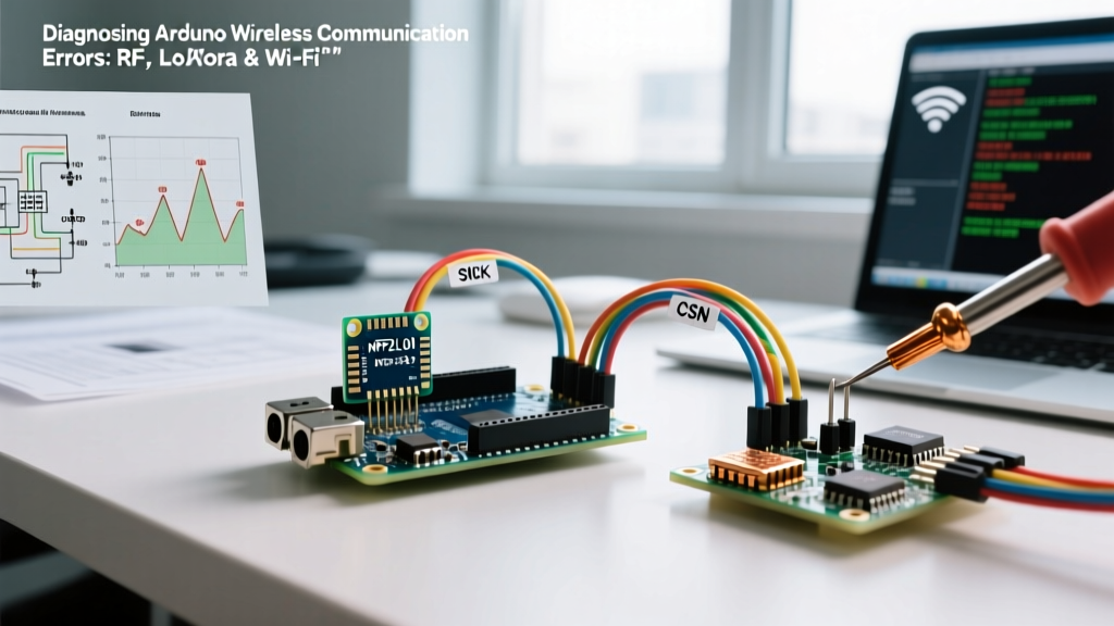
- Hookup: Connect CH0 to SCK, CH1 to MOSI, CH2 to MISO, CH3 to CSN, and CH4 to CE (for nRF24) or DIO0 (for LoRa). Don't forget the common GND.
- Trigger Setup: Set a falling-edge trigger on the CSN (Chip Select) line to capture the exact moment the MCU addresses the radio.
- Timing Verification: For the nRF24L01+, the CE pin must be held HIGH for a minimum of 10µs to trigger a transmission. If your ATmega is running heavy interrupt routines, the CE pulse might be truncated to 3µs, resulting in a silent failure to transmit. The logic analyzer will instantly reveal this timing violation.
Frequently Asked Questions (FAQ)
Why does my wireless range drop when I put the Arduino in a metal enclosure?
A metal enclosure acts as a Faraday cage, attenuating RF signals by 40dB or more. To fix this, you must use an external antenna connected via a U.FL to SMA pigtail cable. Ensure the SMA connector is properly grounded to the enclosure chassis to maintain the antenna's radiation pattern. Never route the RF cable near the Arduino's digital crystal oscillator, as the 16MHz harmonic noise will desensitize the receiver.
Can I use the RadioHead and TMRh20 libraries simultaneously on one Arduino?
No. Both libraries attempt to configure the hardware SPI bus and attach global interrupts. Running an nRF24L01+ (via TMRh20) and a LoRa module (via RadioHead) on the same SPI bus requires manual CSN (Chip Select) management and modifying the library source code to prevent SPI transaction collisions. For dual-radio setups in 2026, it is highly recommended to use a dual-core ESP32, assigning one radio to the SPI bus and the other to the HSPI (Hardware SPI 2) bus, isolating the hardware interfaces entirely.
My LoRa payload arrives, but the last 3 bytes are always corrupted. Why?
This is a classic FIFO buffer overflow. If your MCU is busy executing a blocking function (like updating a slow I2C OLED display) when the LoRa DIO0 interrupt fires, the radio's internal 256-byte FIFO buffer continues to receive data from the air. If the MCU doesn't read the SPI buffer fast enough, the oldest bytes are overwritten or the packet CRC fails. Always use non-blocking display libraries (like U8g2's picture loop) or move the OLED to a secondary I2C bus to ensure the SPI interrupt service routine (ISR) executes in under 50µs.