
The Reality of 8x8 Matrix LED Arduino Troubleshooting
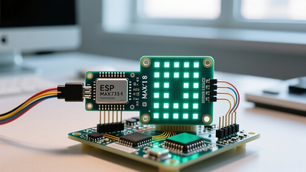
Building an 8x8 matrix LED Arduino project is a rite of passage for makers, but it rarely works perfectly on the first upload. Whether you are building a scrolling marquee, a retro pixel game, or a clock, the underlying hardware usually relies on the MAX7219 LED driver IC. While the Analog Devices MAX7219 Datasheet outlines a robust architecture, real-world implementation is plagued by power delivery bottlenecks, signal degradation, and a rampant counterfeit chip market.
This guide bypasses basic 'check your wiring' advice and dives deep into the electrical and logical failure modes of 8x8 LED matrices. We will diagnose ghosting, flickering, SPI bus collisions, and library conflicts using actionable hardware and software interventions.
Rapid Diagnostic Matrix: Symptoms vs. Root Causes
Before breaking out the multimeter, match your specific visual or compilation error to this diagnostic matrix to isolate the subsystem at fault.
| Observed Symptom | Probable Root Cause | Diagnostic Action |
|---|---|---|
| Random 'ghost' LEDs faintly lit | Missing decoupling capacitance or floating CS pin | Add 100nF ceramic cap across VCC/GND; verify CS pull-up |
| Display flickers during Wi-Fi TX | ESP32/ESP8266 3.3V logic brownout or SPI bus contention | Separate 5V PSU for matrix; use 74AHCT125 level shifter |
| Entire matrix lights up solid white | SPI clock speed too high for counterfeit MAX7219 ASIC | Reduce SPI clock to 1MHz or 2MHz in library initialization |
| Rows and columns are inverted | Common Anode matrix wired to Common Cathode driver | Verify matrix polarity; MAX7219 sinks current (requires CC) |
| Only first module in chain works | DOUT to DIN chain broken or missing termination resistor | Check continuity on ribbon cables; verify cascaded device count |
Deep Dive 1: Power Delivery and the 'Ghosting' Phenomenon
The most common error in an 8x8 matrix LED Arduino setup is 'ghosting'—where unlit LEDs emit a faint glow, or the entire display dims when a new pattern is loaded. This is almost exclusively a power integrity issue.
The Multiplexing Current Math
The MAX7219 does not drive all 64 LEDs simultaneously. It uses multiplexing, illuminating one row (or column) at a time at a high frequency. If you set the segment current to 20mA, a single row of 8 LEDs draws 160mA. Add the IC's internal overhead, and a single 8x8 module can pull peak currents approaching 330mA.
If you daisy-chain four modules and power them directly from the Arduino Uno's 5V pin, you are attempting to pull over 1.3A through the board's USB polyfuse (typically rated for 500mA) or the onboard linear regulator (which will enter thermal shutdown). The resulting voltage sag causes the MAX7219's internal logic to reset unpredictably, leading to ghosting.
Expert Hardware Fix: Never power more than two MAX7219 modules directly from an Arduino's 5V pin. For larger arrays, inject power directly into the module's VCC/GND header pins using an external 5V 2A (minimum) buck converter. Tie the external ground to the Arduino ground to maintain a common SPI reference.
Decoupling Capacitor Requirements
High-frequency switching creates voltage ripple on the power rail. The FC-113 module (the most common cheap 8x8 matrix carrier) often ships with inadequate bulk capacitance. Solder a 10µF electrolytic capacitor and a 100nF (0.1µF) ceramic capacitor in parallel across the 5V and GND pins of the first module in your chain. The ceramic cap handles high-frequency SPI switching noise, while the electrolytic cap provides a local reservoir for multiplexing current spikes.
Deep Dive 2: The 2026 Counterfeit ASIC Epidemic
If your hardware SPI code compiles but the display outputs chaotic noise or lights up entirely white, you are likely a victim of the cloned ASIC market. Genuine Maxim Integrated (now Analog Devices) MAX7219CWG chips cost between $4.00 and $6.00 each in low volumes. The ubiquitous 4-pack FC-113 modules selling for $5.00 on Amazon or AliExpress use reverse-engineered, cloned silicon.
SPI Clock Speed Mismatches
These cloned chips often fail to latch data correctly at the standard 10MHz hardware SPI speeds supported by modern libraries like MajicDesigns MD_MAX72XX. When the clock outpaces the counterfeit chip's internal shift register, data bits smear across adjacent registers, resulting in a 'solid white' or 'static noise' display.
Software Intervention: Throttling the SPI Bus
To diagnose and fix this, you must manually override the SPI clock divider. According to the Arduino SPI Reference, you can adjust the clock speed during initialization. If using the MD_MAX72XX library, modify your setup routine to force a slower clock speed:
#include <MD_MAX72xx.h>
#include <SPI.h>

// Define hardware type and pins
#define HARDWARE_TYPE MD_MAX72XX::FC16_HW
#define MAX_DEVICES 4
#define CS_PIN 10

MD_MAX72XX mx = MD_MAX72XX(HARDWARE_TYPE, CS_PIN, MAX_DEVICES);

void setup() {
  // Force SPI clock to 2MHz to accommodate counterfeit ASICs
  SPI.beginTransaction(SPISettings(2000000, MSBFIRST, SPI_MODE0));
  mx.begin();
  mx.control(MD_MAX72XX::INTENSITY, 8);
  mx.clear();
}
If dropping the speed to 2MHz stabilizes the display, you have confirmed the presence of a sub-par clone chip. You can leave the code as-is, or bit-bang the SPI using the older LedControl library, which is inherently slower and more forgiving of cheap silicon.
Deep Dive 3: Matrix Polarity and Pinout Inversions
Not all raw 8x8 LED matrices are wired identically. They come in two architectures: Common Cathode (CC) and Common Anode (CA).
- Common Cathode: The cathodes (negative terminals) of the LEDs in a row are tied together. The MAX7219 is designed specifically for this topology, as its DIG (digit) pins sink current to ground, while its SEG (segment) pins source current.
- Common Anode: The anodes (positive terminals) are tied together. If you wire a CA matrix to a standard MAX7219 breakout board, the current flow logic is inverted. The result is a display where rows act as columns, columns act as rows, and ghosting is severe because the internal protection diodes of the IC are being forward-biased incorrectly.
The Fix: If you are soldering a raw matrix to a bare MAX7219 IC, use a multimeter in diode-test mode to map the row/column pins before soldering. If you must use a Common Anode matrix with a MAX7219, you will need to transpose your pixel arrays in software (swapping X and Y coordinates) and accept a reduction in maximum brightness due to the IC's internal voltage drop characteristics when operating outside its intended sinking topology.
Deep Dive 4: Logic Level Translation for 3.3V MCUs
When migrating an 8x8 matrix LED Arduino project to a 3.3V microcontroller like the ESP32 or Raspberry Pi Pico, you introduce a critical logic threshold error. The MAX7219 requires a minimum of 2.0V on the DIN, CLK, and LOAD pins to register a logic HIGH. While a 3.3V MCU technically exceeds 2.0V, long jumper wires act as antennas, introducing capacitance that droops the 3.3V signal below the 2.0V threshold during high-speed SPI transitions.
Implementing a Level Shifter
Do not rely on direct 3.3V-to-5V connections for chains longer than two modules. Insert a 74AHCT125 or 74HCT245 logic level translator between the MCU and the first MAX7219 module. The 74AHCT family is specifically designed to accept 3.3V logic inputs and output a clean, fast-edge 5V signal, eliminating SPI timing jitter and ensuring the LOAD (CS) pin latches the shift register precisely on the 16th clock cycle.
Final Pre-Flight Troubleshooting Checklist
Before blaming a faulty module, run through this ordered diagnostic sequence:
- Verify VCC/GND Continuity: Ensure the external 5V supply shares a common ground with the MCU. Without a common ground, SPI signals have no reference plane.
- Isolate the Chain: Disconnect all modules except the first one. Run a basic test sketch. If it works, the issue is a broken DOUT-to-DIN trace on one of the downstream PCBs.
- Check the CS Pin: The MAX7219 LOAD (CS) pin is active LOW. If your MCU leaves the CS pin floating during boot, the matrix will latch SPI noise from other peripherals. Add a 10kΩ pull-up resistor to 5V on the CS line.
- Confirm Hardware Type: Libraries require the correct hardware mapping. An FC-113 module uses a different internal PCB trace layout than an FC-16 module. Defining
FC16_HWinstead ofGENERIC_HWin your library initialization will instantly fix 'scrambled' or mirrored text errors.
By addressing power integrity, SPI clock tolerances, and logic level thresholds, you can transform a flickering, unreliable 8x8 matrix LED Arduino project into a robust, commercial-grade display system.