
Quick Reference: Standard Board I/O Capacities
When scaling up a complex project, makers frequently encounter the physical and electrical Arduino limitations. Multiple output pins are often required for LED matrices, relay arrays, sensor multiplexing, or robotics, but standard development boards quickly run out of available I/O. Before attempting to bypass these limits, it is critical to understand the baseline hardware constraints of the most common microcontroller boards used in the maker community.
| Development Board | Core MCU | Digital I/O Pins | PWM Channels | Analog Inputs |
|---|---|---|---|---|
| Arduino Uno R3 / R4 | ATmega328P / RA4M1 | 14 (20) | 6 (12) | 6 (12) |
| Arduino Nano | ATmega328P | 14 (22) | 6 | 8 |
| Arduino Mega 2560 | ATmega2560 | 54 | 15 | 16 |
| Arduino Nano 33 IoT | SAMD21 Cortex-M0+ | 14 (22) | 11 | 8 |
Note: Values in parentheses indicate total accessible GPIO pins when utilizing analog pins as digital I/O or accessing hidden board headers.
Frequently Asked Questions: Navigating Pin & Current Limitations
Q: What is the actual current limit when driving multiple output pins simultaneously?
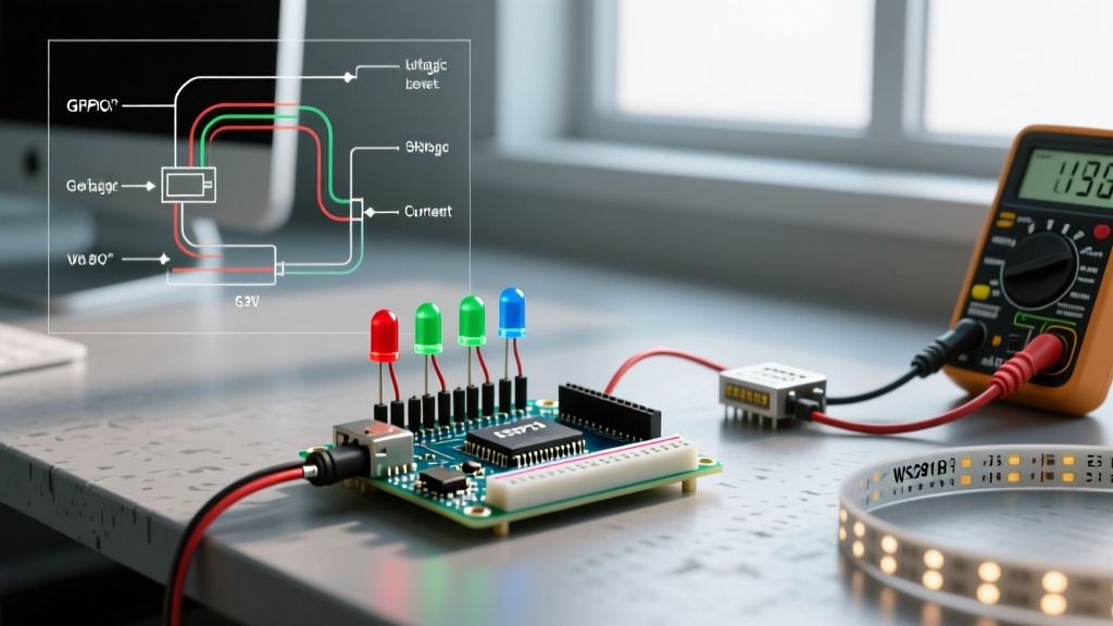
The most dangerous Arduino limitation regarding multiple output pins is not the physical number of pins, but the aggregate current capacity of the microcontroller. Many beginners assume that if a single pin can safely source 20mA, they can draw 20mA from all 14 digital pins simultaneously (totaling 280mA). This will permanently damage the silicon.
Critical Hardware Rule: The ATmega328P has an absolute maximum current rating of 200mA for the combined VCC and GND pins. For long-term reliability in 2026 production environments, engineers recommend keeping the total aggregate MCU current draw below 150mA.
If you attempt to drive 10 standard 5mm LEDs (drawing 15mA each) directly from the Uno's digital pins, you will pull 150mA. While this is technically within the absolute maximum threshold, it leaves almost zero headroom for the MCU's own internal logic operations, potentially causing brownouts, erratic behavior, or thermal throttling of the onboard 5V linear regulator.
Q: How can I bypass digital pin limitations using shift registers?
When you need to control a high volume of simple digital outputs (like relays, indicator LEDs, or solenoid valves), the industry-standard workaround is the serial-in, parallel-out shift register. The most ubiquitous chip for this is the Texas Instruments SN74HC595.
By utilizing the SPI or standard GPIO bit-banging protocols, you can control 8 distinct output pins using only 3 microcontroller pins (Data, Clock, and Latch). Furthermore, these ICs are daisy-chainable. You can wire the serial output (QH') of one chip to the serial input of the next, allowing you to control 16, 24, or even 64 outputs using the exact same 3 MCU pins.
- Component Cost: Generic SN74HC595N DIP-16 ICs cost between $0.40 and $0.80 in single quantities as of 2026.
- Current Limits: Each pin can source/sink up to 35mA, but the total continuous current for the entire IC package must not exceed 70mA.
- Best For: LED cubes, 7-segment displays, and low-power relay driver arrays (when paired with ULN2803 Darlington arrays).
Q: What if I need multiple PWM outputs for servos or high-speed dimming?
Shift registers only provide basic HIGH/LOW digital states. If your project requires multiple Pulse Width Modulation (PWM) signals—such as driving 12 continuous-rotation servos for a robotic arm or dimming an array of high-power MOSFETs for architectural lighting—the standard Arduino hardware PWM pins will fall short.
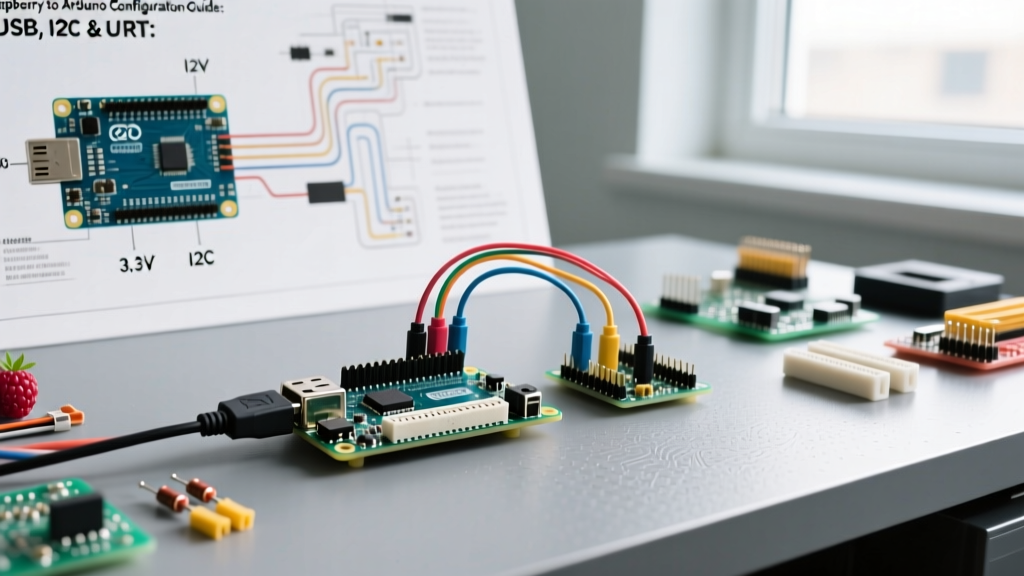
The optimal hardware solution is an I2C-based PWM driver, specifically the NXP PCA9685. This chip communicates over the I2C bus (using only the A4 and A5 pins on an Uno) and provides 16 channels of independent, 12-bit hardware PWM.
Because the PCA9685 handles the PWM timing internally via an onboard oscillator, it completely frees the Arduino's CPU from software-based PWM interrupts. You can daisy-chain up to 62 PCA9685 boards on a single I2C bus by adjusting the A0-A5 address jumper pads, theoretically yielding 992 independent PWM channels from just two Arduino pins.
Q: Are there software bottlenecks when toggling many pins simultaneously?
Yes. The standard Arduino digitalWrite() function is notoriously slow because it includes overhead for checking timer configurations, validating pin numbers, and ensuring compatibility across different board architectures. Executing digitalWrite() takes approximately 3 to 5 microseconds per call. If you are attempting to multiplex a large LED matrix or drive a high-speed DAC using resistor ladders, this software latency will cause visible flickering or signal degradation.
To overcome this software-side Arduino limitation, multiple output pins should be manipulated using Direct Port Manipulation. By writing directly to the microcontroller's hardware registers (e.g., PORTD, DDRB), you can toggle up to 8 pins simultaneously in a single clock cycle (62.5 nanoseconds on a 16MHz Uno).
// Standard slow method
pinMode(2, OUTPUT); pinMode(3, OUTPUT); pinMode(4, OUTPUT);
digitalWrite(2, HIGH); digitalWrite(3, HIGH); digitalWrite(4, HIGH);

// Direct Port Manipulation (Pins 0-7 on PORTD)
DDRD = B00011100; // Set pins 2, 3, 4 as outputs
PORTD = B00011100; // Set pins 2, 3, 4 HIGH instantly
Comparison Matrix: Pin Expansion Techniques
Selecting the correct expansion method depends entirely on your project's specific requirements regarding speed, current, and signal type. Use the matrix below to architect your hardware stack.
| Expansion Technique | MCU Pins Used | Outputs Gained | Signal Type | Approx. Cost (2026) | Primary Limitation |
|---|---|---|---|---|---|
| 74HC595 Shift Register | 3 (SPI/GPIO) | 8 per IC (Infinite) | Digital (High/Low) | $0.50 / IC | 70mA max total IC current; no hardware PWM. |
| MCP23017 I2C Expander | 2 (I2C) | 16 per IC (Up to 8 ICs) | Digital (High/Low) | $1.20 / IC | I2C bus capacitance limits high-speed toggling. |
| PCA9685 PWM Driver | 2 (I2C) | 16 per IC (Up to 62 ICs) | 12-bit Hardware PWM | $6.00 (Breakout) | Designed for LEDs/Servos; not for high-speed data. |
| Charlieplexing | N pins | N * (N - 1) | Digital / Multiplexed | $0.00 (Code only) | Complex wiring; only 1 LED on per plane at a time; high CPU load. |
| Direct Port Manipulation | N/A (Native) | Up to 8 per Register | Digital (High Speed) | $0.00 (Code only) | Highly architecture-dependent; breaks code portability. |
Summary: Designing for Scale
Understanding Arduino limitations regarding multiple output pins is the dividing line between a hobbyist prototype and a robust, production-ready electronic system. Never rely solely on the physical pin count printed on a board's silkscreen; always calculate the aggregate current draw against the MCU's VCC/GND thresholds. For simple digital expansion, shift registers remain the most cost-effective solution. For complex analog or servo control, offloading the timing requirements to an I2C PWM driver like the PCA9685 ensures your microcontroller's CPU remains free to handle core logic and sensor polling.