
Defining the Arduino Domotic Paradigm
When makers transition from standalone prototypes to whole-home automation, they enter the realm of Arduino domotic systems. Unlike consumer-grade wireless ecosystems (like Tuya or Zigbee-based Philips Hue), a true domotic architecture built on microcontrollers prioritizes deterministic latency, local processing, and hardwired reliability. In 2026, with the rise of the Matter protocol and local-first smart home philosophies, building a custom MCU-based domotic network is no longer just a hobbyist experiment—it is a robust alternative to cloud-dependent commercial gear.
"A domotic system is only as reliable as its physical layer. Wireless is for convenience; hardwired differential signaling is for infrastructure."
This guide deconstructs the core architecture of an Arduino-based domotic network, moving beyond basic breadboard wiring into industrial-grade topology, bus capacitance limits, and isolated sensor nodes.
Topology Matrix: Choosing Your Physical Layer
The most common failure point in beginner Arduino domotic projects is attempting to run I2C sensors over long distances. Selecting the correct communication topology dictates your maximum cable run, node cost, and noise immunity.
| Protocol | Topology | Max Distance | Node Cost (Approx) | Ideal Domotic Application |
|---|---|---|---|---|
| I2C | Star / Multi-drop | < 1 meter | $1.50 | Internal enclosure sensors, local displays |
| RS-485 | Daisy-Chain Bus | 1,200 meters | $4.50 - $6.00 | Whole-home hardwired wall switches, HVAC |
| CAN Bus | Multi-master | 40m (at 1Mbps) | $3.00 | High-noise environments, motorized blinds |
| LoRa (SX1276) | Star / Mesh | 5km+ (Line of Sight) | $8.00 | Outbuildings, irrigation, gate controls |
The Central Gateway: Beyond the Arduino Mega
Historically, the Arduino Mega 2560 was the default gateway for domotic projects due to its abundance of UART and I/O pins. However, as of 2026, the Mega is entirely obsolete for modern smart home gateways. It lacks native networking, requires cumbersome Ethernet shields, and struggles with the TLS encryption required by modern MQTT brokers.
The ESP32-S3 Standard
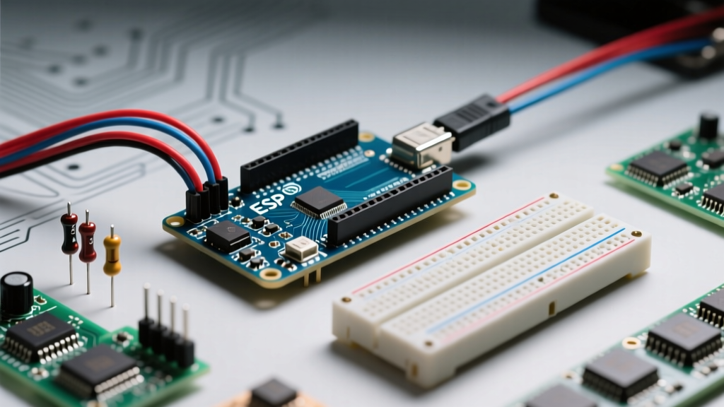
The industry standard for an Arduino domotic gateway is now the ESP32-S3. Priced between $7 and $12 for a fully populated DevKitC-1 board, the S3 offers dual-core processing at 240MHz, native Wi-Fi 4, Bluetooth 5 (LE), and crucially, native USB OTG. This allows the ESP32-S3 to act simultaneously as a Wi-Fi MQTT bridge and a USB-CDC serial device for local debugging, all without requiring external USB-to-Serial ICs like the CH340 or CP2102.
For gateways requiring hardwired RS-485 or CAN bus, makers pair the ESP32-S3 with isolated transceiver shields, routing the domotic data to a local Home Assistant MQTT broker for logic processing and dashboard visualization.
Hardwired Sensor Networks: Overcoming Physical Limits
When wiring sensors across a home, you must respect the electrical characteristics of the protocols. Here are the specific failure modes and engineering solutions for the two most common domotic wiring schemes.
The I2C Capacitance Trap
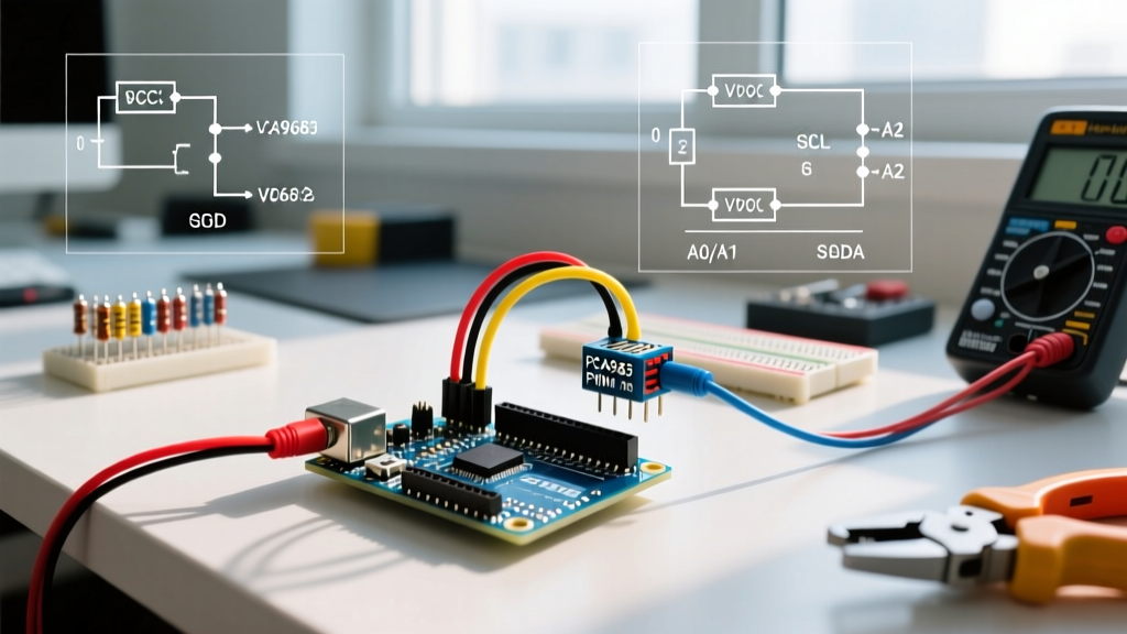
The I2C specification limits total bus capacitance to 400pF. A standard CAT6 Ethernet cable has a wire-to-wire capacitance of roughly 50pF per meter. If you run a DHT22 or BME280 sensor just 8 meters away from your Arduino using CAT6, you will hit the 400pF limit. The signal edges will degrade, the pull-up resistors will fail to bring the line high in time, and the I2C bus will lock up, crashing your MCU.
- The Amateur Fix: Lowering the I2C clock speed from 400kHz to 100kHz (buys a little distance, but unreliable).
- The Engineering Fix: Use an I2C bus extender IC like the NXP P82B96 (approx. $3.50). This chip converts the I2C signals into a differential current-mode transmission, allowing runs up to 20 meters over standard twisted pair without capacitance issues.
RS-485: The Backbone of Domotic Wiring
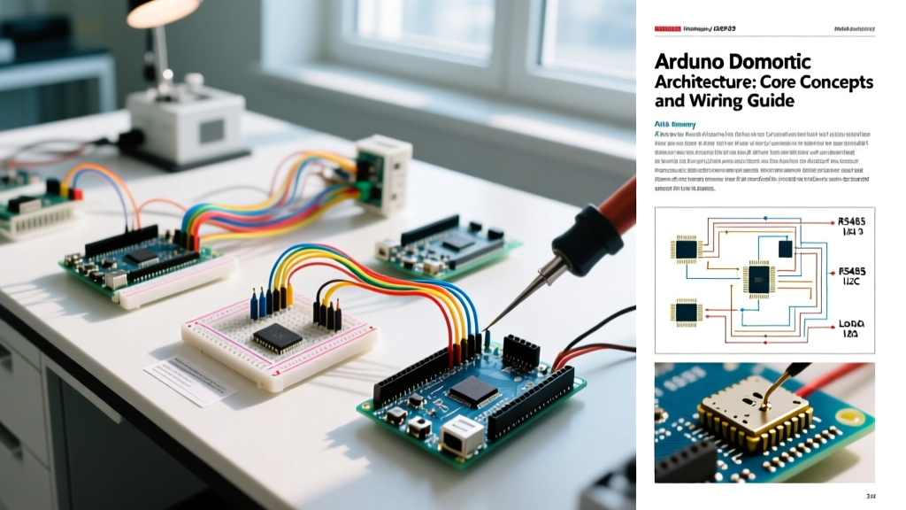
For whole-home domotics, RS-485 is the undisputed king. It uses differential signaling, meaning it measures the voltage difference between the A and B wires, rendering it completely immune to the common-mode noise generated by HVAC systems and LED drivers. According to Texas Instruments' RS-485 design guidelines, a properly terminated bus can support up to 32 unit loads over 1.2 kilometers.
Step-by-Step: Building an Isolated RS-485 Domotic Node
Beginners often use the MAX485 chip ($0.50) for RS-485 nodes. This is a critical mistake in home automation. The MAX485 shares a ground reference with the MCU. If a ground loop occurs between the central gateway and a remote wall switch, 24VAC from a stray HVAC wire can instantly vaporize your Arduino's voltage regulator.
Instead, use an isolated transceiver like the Analog Devices ADM2587 ($5.20). It features an integrated isolated DC-DC converter, providing 5kV of galvanic isolation.
- Power Isolation: Feed 5V into the VDD1 pin of the ADM2587. The internal oscillator will generate the isolated 5V on VDD2, which powers the RS-485 line drivers and the remote sensor.
- Signal Routing: Connect the Arduino TX/RX pins to the T1/R1 pins on the logic side. The T2/R2 pins connect to the A/B differential bus.
- Cable Selection: Use CAT6 cable. Assign the Orange pair for RS-485 A/B, the Blue pair for isolated GND, and the Brown pair for isolated VCC.
- Termination: Solder a 120-ohm resistor across the A and B pins only at the physical first and last nodes of the daisy chain. Intermediate nodes must not have termination resistors.
- Biasing: To prevent the bus from floating into an undefined state when all Arduinos are in receive mode (which causes phantom interrupts), add a 560-ohm pull-up resistor on the A line (to VCC) and a 560-ohm pull-down resistor on the B line (to GND) at the master gateway.
Software Architecture: Async MQTT and Local State
On the software side, an Arduino domotic node must never block its main loop. Using the standard PubSubClient library can cause watchdog resets if the Wi-Fi drops or the MQTT broker lags, as the client.publish() function is synchronous.
For ESP32-based gateways, utilize the AsyncMqttClient library. This leverages the ESP32's FreeRTOS capabilities, handling network handshakes on the secondary core while the primary core continues polling hardwired sensors. Furthermore, implement local state retention: if the MQTT broker goes offline, the domotic node should cache its sensor readings in non-volatile memory (like the ESP32's Preferences library) and burst-upload the data once the connection is restored.
Summary
Building a reliable Arduino domotic system requires abandoning the "jumper wire" mentality. By upgrading to ESP32-S3 gateways, respecting I2C capacitance limits, and deploying galvanically isolated RS-485 nodes, you create a smart home infrastructure that rivals commercial KNX or Control4 systems, but at a fraction of the cost and with total open-source transparency.