
The Definitive Quick Reference for Arduino Components
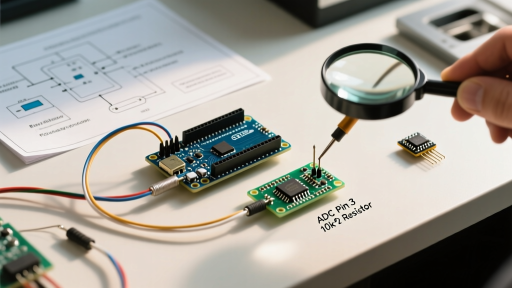
Building reliable, production-grade prototypes requires moving beyond basic starter kits. Whether you are designing an IoT environmental monitor or a high-torque robotic chassis, selecting the correct components for Arduino ecosystems dictates the success and longevity of your project. This FAQ and quick reference guide cuts through generic advice, providing exact part numbers, electrical tolerances, and 2026 market pricing to help you make informed engineering decisions.
Quick Reference Matrix: Essential Hardware
Before diving into specific troubleshooting scenarios, review this matrix of foundational hardware. These selections prioritize reliability, modern architecture, and broad community support.
| Component Category | Recommended Model / Part Number | Avg 2026 Price | Key Technical Specification |
|---|---|---|---|
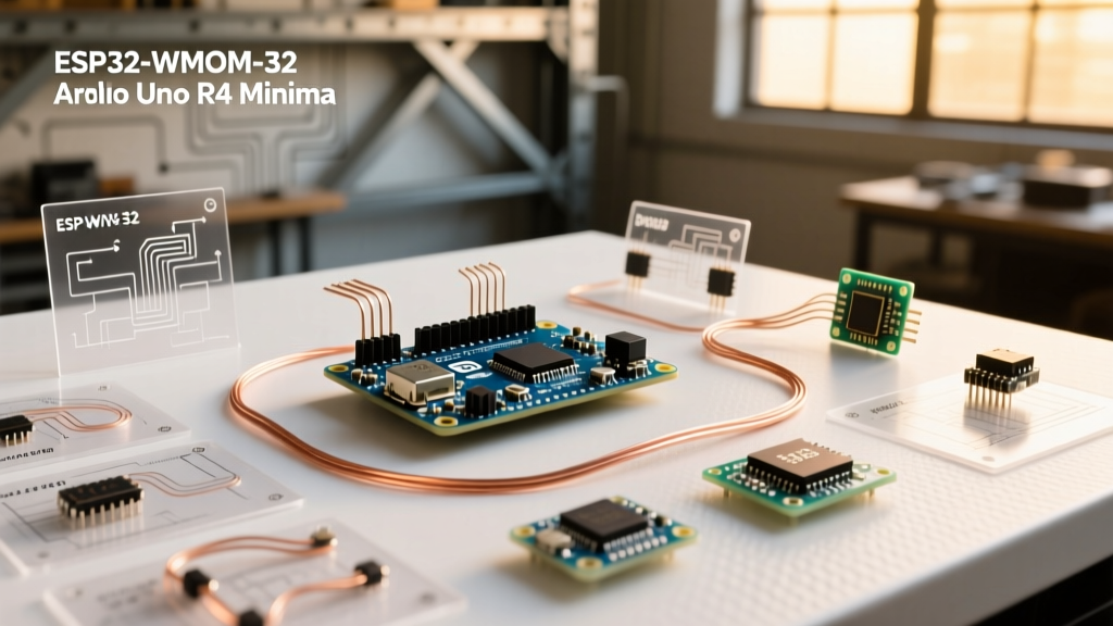
| Microcontroller Board | Arduino Uno R4 Minima | $20.00 | Renesas RA4M1 (32-bit ARM Cortex-M4), 48MHz |
| Environmental Sensor | Adafruit BME280 (PID 2652) | $14.95 | I2C/SPI, ±1°C accuracy, 0.01 hPa resolution |
| Motor Driver | Pololu TB6612FNG (Item 713) | $8.95 | Dual channel, 1.2A continuous, 0.5V MOSFET drop |
| Logic Level Shifter | SparkFun Bi-Directional (BOB-12009) | $3.50 | BSS138 MOSFET-based, safe for 3.3V/5V I2C |
| Breadboard Wiring | 22 AWG Solid Core (Uxcell/Generic) | $12.00 / spool | Pre-tinned copper, fits standard 0.1" headers |
Frequently Asked Questions (FAQ)
Q1: What are the absolute bare-minimum components for Arduino to get started reliably?
While many cheap kits flood the market with low-tolerance parts, a reliable bare-minimum workbench requires specific grades of components. Skip the 8-bit ATmega328P-based Uno R3 for new designs; the Arduino Uno R4 Minima is the 2026 standard, offering a 32-bit ARM Cortex-M4 processor, native USB-C, and a 12-bit DAC.
Beyond the board, you need:
- Prototyping Surface: A 400-tie-point solderless breadboard with a continuous power rail. Avoid 830-point boards for high-frequency signals due to higher parasitic capacitance.
- Wiring: 22 AWG solid-core wire for breadboard jumps. For connections to moving parts or external enclosures, use 26 AWG stranded silicone wire to prevent metal fatigue and breakage.
- Passives: A 1/4W 5% carbon film resistor kit (E12 series). You will heavily rely on 220Ω and 330Ω resistors for current-limiting standard 5mm LEDs (calculating a safe 15mA forward current at 5V).
Q2: Which environmental sensors offer the best reliability for long-term monitoring?
Historically, the DHT11 and DHT22 were the default choices for hobbyists. In 2026, these are considered obsolete for any project requiring accuracy. The DHT11 uses a capacitive humidity sensor that frequently locks up and requires a hard power-cycle to reset, while the DHT22 suffers from long-term drift in high-humidity environments.
The definitive upgrade is the Bosch BME280. The Adafruit BME280 breakout integrates temperature, pressure, and humidity into a single I2C package. It draws only 3.6 µA in sleep mode, making it ideal for battery-powered nodes. Edge Case Warning: Ensure you check the I2C address on your specific breakout board. Some manufacturers hardwire the address to 0x76, while others use 0x77. If you need multiple sensors on one bus, you must use a TCA9548A I2C multiplexer.
Q3: How do I choose the right motor driver for robotics projects?
The L298N dual H-bridge has dominated beginner tutorials for a decade, but it is fundamentally flawed for modern, battery-operated robotics. Because it uses bipolar junction transistors (BJTs), the L298N suffers from a voltage drop of roughly 2.0V across the chip. If you supply 6V from a battery pack, your motors only receive 4V, resulting in massive efficiency losses and excess heat.
Instead, use MOSFET-based drivers like the TB6612FNG. It handles 1.2A continuous current per channel (up to 3.2A peak) with a voltage drop of only 0.5V. This translates to significantly longer battery life and higher torque delivery to your DC gear motors. For stepper motors (like the NEMA 17), bypass H-bridges entirely and use a chopper driver like the TMC2209, which supports silent microstepping and UART configuration.
Q4: What is the most common failure mode when wiring Arduino components?
The most catastrophic and common failure mode is exceeding GPIO current limits and omitting a common ground.
Engineering Rule of Thumb: Never power high-draw actuators directly from the microcontroller's 5V or 3.3V pins. The onboard linear regulator (or USB trace) will overheat and fail.
Furthermore, when integrating external power supplies for servos or motors, makers often forget to connect the ground (GND) of the external supply to the GND of the Arduino. Without a common ground reference, the logic signals sent to motor drivers or relays will float, causing erratic behavior, missed pulses, or permanent silicon damage to the I/O pins. Always tie your grounds together at a single star-ground point to prevent ground loops.
Q5: How do I safely interface 3.3V sensors with 5V Arduino boards?
While the Arduino Uno R4 operates at 5V, many modern sensors (like the BME280 or various LiDAR modules) operate strictly at 3.3V. Sending a 5V logic HIGH from the Arduino's SDA/SCL pins into a 3.3V sensor's I2C lines will degrade the sensor's internal protection diodes over time, eventually leading to total component failure.
To solve this, you must use a Logic Level Converter. Do not rely on simple voltage divider circuits for I2C lines; the pull-up resistors and parasitic capacitance will distort the square wave, causing communication timeouts. Use a bidirectional MOSFET-based level shifter (like the SparkFun BOB-12009 based on the BSS138 transistor). Connect the 5V side to the Arduino, the 3.3V side to the sensor, and ensure both sides share a common ground.
Power Supply Edge Cases: Beyond the USB Cable
When your project leaves the desk and enters the field, power delivery becomes the primary point of failure. Here is how to handle specific power scenarios:
- High-Torque Servos (e.g., MG996R): A single MG996R can draw up to 2.5A at stall. Powering this from the Arduino barrel jack will cause an immediate brownout, resetting the microcontroller. Use a dedicated LM2596 buck converter module set to 5.0V, powered by a 2S or 3S LiPo battery, to supply the servos independently.
- Wireless Transmission Spikes: Modules like the ESP8266 or cellular LTE modems draw brief current spikes (up to 500mA) during RF transmission. Place a 470µF electrolytic capacitor and a 0.1µF ceramic capacitor in parallel across the module's VCC and GND pins to smooth out transient voltage dips.
- Reverse Polarity Protection: When wiring custom battery packs, always place a P-channel MOSFET (like the IRF9540) or a simple Schottky diode on the positive rail to protect your components if the battery is connected backward.
Summary
Sourcing the right components for Arduino projects is about prioritizing electrical safety, signal integrity, and modern efficiency over legacy tutorial defaults. By upgrading to MOSFET motor drivers, utilizing proper logic level shifting, and respecting current limits, you transition from building fragile prototypes to engineering robust, field-ready hardware.